
Natural gas pipeline control valve with specific detection function

A technology for natural gas pipelines and control valves, applied in pipeline systems, valve details, valve devices, etc., can solve problems such as leakage, no buffer structure, and reduce equipment reliability, and achieve the effect of simple equipment structure.

Inactive Publication Date: 2021-04-20
杨桂英
View PDF0 Cites 0 Cited by
  • Summary
  • Abstract
  • Description
  • Claims
  • Application Information

AI Technical Summary

Problems solved by technology

[0002] The existing natural gas valve control valve has many shortcomings. Firstly, it is because it does not know whether the valve has reached the limit position that has been locked or opened when the valve is switched on and off, and because the structure of the existing equipment for driving the valve does not There is no corresponding buffer structure, and the valve cannot be buffered and switched well, which may affect the actual service life and reliability of the valve with a certain probability. More importantly, due to the existing above-mentioned design, the valve equipment is damaged. It is impossible to effectively maintain and protect the corresponding valve switch structure, and if there is a corresponding leakage in the pipeline, it is impossible to know where the leakage or leakage occurs, and it is impossible to adequately protect the leakage of the pipeline, so that the corresponding The function of timely and efficient temporary sealing of leaked natural gas greatly reduces the reliability of the actual use of the equipment

Method used


Image

  • Natural gas pipeline control valve with specific detection function
  • Natural gas pipeline control valve with specific detection function
  • Natural gas pipeline control valve with specific detection function

Examples


Embodiment Construction

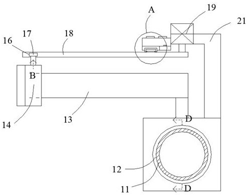
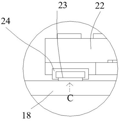
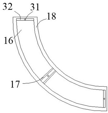
[0020] Such as Figure 1-Figure 5 As shown, the present invention is described in detail. For the convenience of description, the orientations mentioned below are now stipulated as follows: figure 1 The up, down, left, right, front and back directions of the projection relationship are consistent. A natural gas pipeline control valve with a specific detection function of the present invention includes a pipeline 11. A natural gas valve is arranged on the outside of the pipeline 11. A swing valve stem 13 is arranged inside the natural gas valve. One side of the swing valve stem 13 is provided with a rotation safety device that is fixed to the natural gas valve and can calibrate the swing of the swing valve stem 13 to an accurate position and can provide a preload margin to maintain stable locking. The outer surface of the pipeline 11 is provided with There are several airbags 12, and the airbags 12 are provided with detection and protection devices for wrapping the pipeline 11 ...


PUM


Abstract

The invention discloses a natural gas pipeline control valve with a specific detection function. The natural gas pipeline control valve comprises a pipeline, wherein the outer side of the pipeline is provided with a natural gas valve, the natural gas valve is internally provided with a swing valve rod, one side of the swing valve rod is provided with a revolving safety device which is fixed to the natural gas valve, can calibrate the swing valve rod to enable the swing valve rod to swing to an accurate position and can provide pre-tightening allowance to keep stable locking, the outer surface of the pipeline is provided with a plurality of air bags, and each air bag is internally provided with a detection protection device which is used for wrapping the pipeline in all directions and can perform detection and preliminarily prevent natural gas leakage. According to the natural gas pipeline control valve, whether the natural gas valve is closed to a locking position or reaches a complete opening position or not can be detected, a revolving structure of the natural gas valve can be buffered and pre-tightened through a spring, and the function of performing pre-detection and preliminarily preventing natural gas pipeline leakage is achieved.

Description

technical field [0001] The invention relates to the technical field of natural gas pipeline valve equipment, in particular to a natural gas pipeline control valve with a specific detection function. Background technique [0002] The existing natural gas valve control valve has many shortcomings. Firstly, it is because it does not know whether the valve has reached the limit position that has been locked or opened when the valve is switched on and off, and because the structure of the existing equipment for driving the valve does not There is no corresponding buffer structure, and the valve cannot be buffered and switched well, which may affect the actual service life and reliability of the valve with a certain probability. More importantly, due to the existing above-mentioned design, the valve equipment is damaged. It is impossible to effectively maintain and protect the corresponding valve switch structure, and if there is a corresponding leakage in the pipeline, it is impo...

Claims


Application Information

Patent Timeline
Patent Type & Authority Applications(China)
IPC IPC(8): F17D5/04F17D3/01F16K31/04F16K31/46F16K37/00F16F15/067
Inventor 杨桂英
Owner 杨桂英
Learn More