Pipe machining equipment

A technology for processing equipment and pipes, which is applied in the field of automation equipment and can solve problems such as low efficiency of cold shrinkable pipes

Pending Publication Date: 2021-04-20
SHENZHEN WOER HEAT SHRINKABLE MATERIAL
View PDF0 Cites 0 Cited by
  • Summary
  • Abstract
  • Description
  • Claims
  • Application Information

AI Technical Summary

Problems solved by technology

[0003] In the related technology, when expanding the cold-shrinkable tube, it is necessary to manually put the cold-shrinkable tube into the expansion mold of the hose expander for end expansion, and then manually insert the cold-shrinkable tube into the inflatable expander for overall expansion. The entire operation process Manual feeding and retrieving transfer operations are required, and the efficiency of cold shrink tube expansion processing is low

Method used


Image

  • Pipe machining equipment
  • Pipe machining equipment
  • Pipe machining equipment

Examples


Embodiment Construction

[0070] The following will clearly and completely describe the technical solutions in the embodiments of the present invention with reference to the accompanying drawings in the embodiments of the present invention. Obviously, the described embodiments are only part of the embodiments of the present invention, not all of them. Based on the embodiments of the present invention, all other embodiments obtained by persons of ordinary skill in the art without creative efforts fall within the protection scope of the present invention.

[0071] It should be noted that all directional indications (such as up, down, left, right, front, back...) in the embodiments of the present invention are only used to explain the relationship between the components in a certain posture (as shown in the accompanying drawings). Relative positional relationship, movement conditions, etc., if the specific posture changes, the directional indication will also change accordingly.

[0072] In the present in...


PUM


Abstract

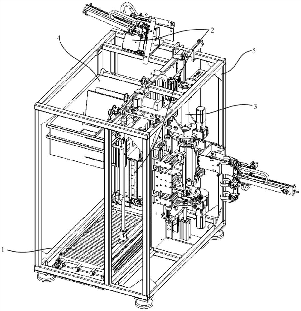
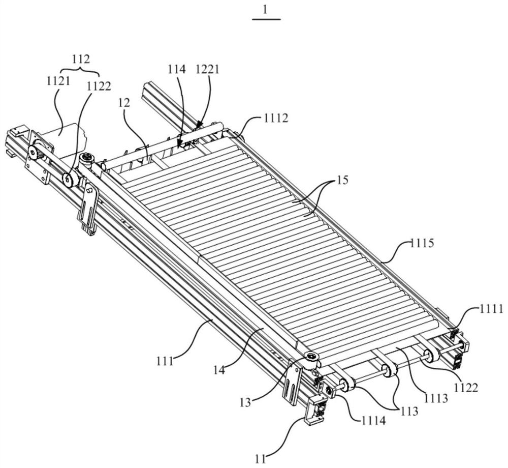
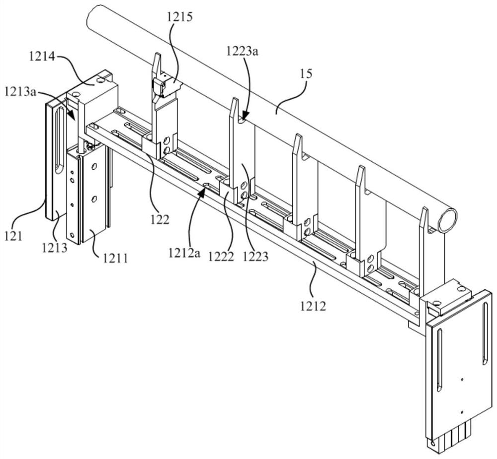
The invention discloses pipe machining equipment. The pipe machining equipment comprises a rack, a first pipe feeding device, a pipe taking device and a pipe expanding device, the first pipe feeding device comprises a conveying table and a first material distributing assembly, the conveying table is provided with a feeding end and a discharging end which are oppositely arranged, and the conveying table is used for conveying a first pipe from the feeding end to the discharging end; the first material distributing assembly comprises a jacking mechanism and a material distributing plate arranged at the output end of the jacking mechanism, the jacking mechanism is arranged at the discharging end, and a material distributing groove is formed in the side, facing the discharging end, of the material distributing plate; when a first pipe enters the material distributing groove, the jacking mechanism drives the material distributing plate to rise so as to lift the first pipe to be separated from the conveying table; the material taking device is arranged on the rack and used for transferring the pipes; and the pipe expanding device is arranged on the rack and used for expanding the first pipe. By means of the pipe machining equipment, automatic feeding, material taking, transferring and expanding machining can be conducted on the pipes.

Description

technical field [0001] The invention relates to the technical field of automation equipment, in particular to a pipe processing equipment. Background technique [0002] Pipes are widely used in industrial production. In industrial production, it is sometimes necessary to socket and assemble cold-shrinkable tubes with other pipes to produce combined pipes. During the socketing process of the cold-shrinkable tube and other tubes, the cold-shrinkable tube needs to be expanded first to facilitate the insertion of other tubes. [0003] In related technologies, when expanding the cold-shrinkable tube, it is necessary to manually put the cold-shrinkable tube into the expansion mold of the rubber hose expansion machine for end expansion, and then manually insert the cold-shrinkable tube into the inflatable expansion machine for overall expansion. The entire operation process It is necessary to manually carry out feeding and retrieving transfer operations, and the efficiency of expa...

Claims


Application Information

Patent Timeline
Patent Type & Authority Applications(China)
IPC IPC(8): B29C55/24B29C31/08
Inventor 王成张维波秦英凡
Owner SHENZHEN WOER HEAT SHRINKABLE MATERIAL
Why Eureka
Try Eureka