Magnetic field shielding device convenient to disassemble and assemble and assembling method thereof
An assembly method and technology of shielding device, applied in the direction of magnetic field/electric field shielding, electrical components, etc., can solve the problems of inability to apply flowmeter products, etc., achieve the effects of ingenious structural design, easy disassembly and installation, and guaranteed measurement effect
- Summary
- Abstract
- Description
- Claims
- Application Information
AI Technical Summary
Problems solved by technology
Method used
Image
Examples
Embodiment 1
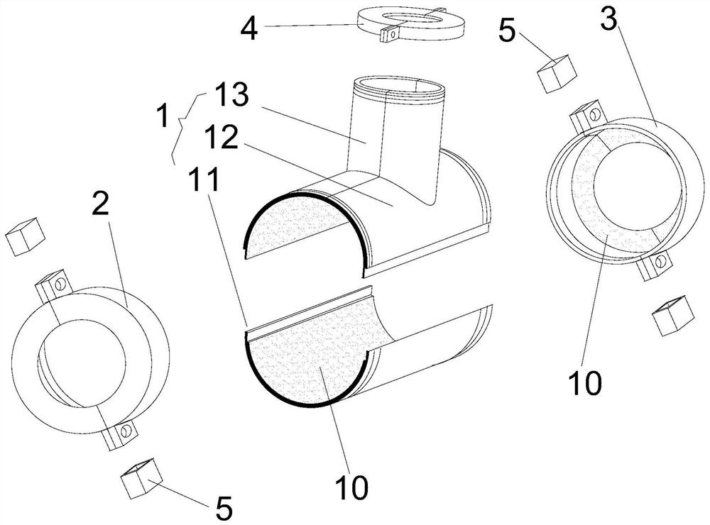
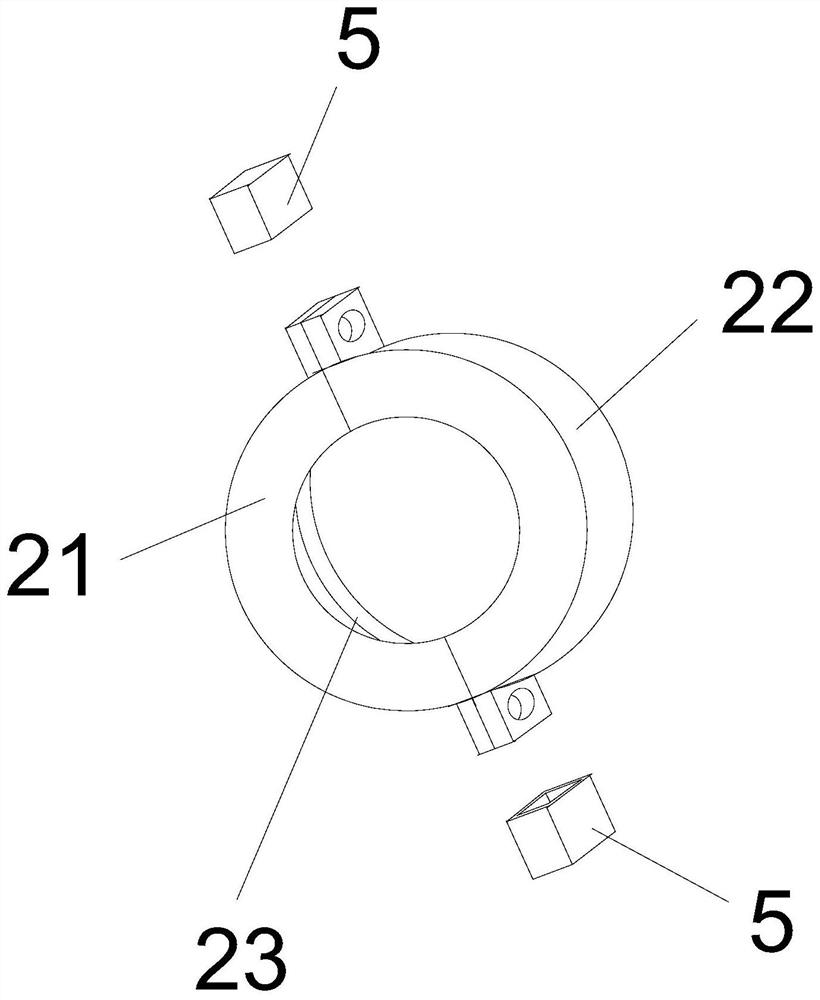
[0046] like figure 1 As shown, the present embodiment provides a magnetic field shield that is easy to assemble and disassemble, and the magnetic field shield is used to be sleeved on the periphery of the flowmeter 100 to shield the magnetic signal of the surrounding environment of the flowmeter 100; the magnetic field shield includes: shielding Cover 1, first cuff 2, second cuff 3, and third cuff 4.
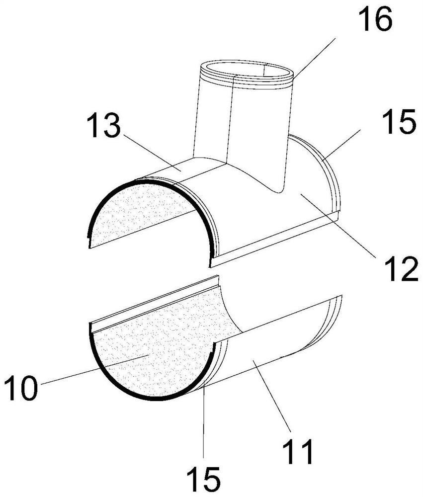
[0047] like figure 2 As shown, the shielding cover 1 includes a detachable first cover body 11, a second cover body 12, and a third cover body 13; the combination of the first cover body 11, the second cover body 12 and the third cover body 13 contains Two cylindrical cavities, wherein the horizontal part is the first cylindrical cavity, and the vertical part is the second cylindrical cavity; the first cylindrical cavity and the second cylindrical cavity are connected in an inverted "T" shape; along the Half-cut the first cylindrical cavity on the horizontal plane, and the ob...
Embodiment 2
[0057] like Figure 7 As shown, the difference between this example and Embodiment 1 is: the magnetic field shielder provided in the embodiment of the present invention for easy disassembly also includes a limit bolt 6; 1. Bolt holes 61 are set on the sides of the left second hoop portion 31 and the right second hoop portion 32, and the bolt holes 61 are located on the unthreaded part of the first hoop 2 and the second hoop 3, and the limit bolt 6 The bolt body is screwed into the shielding case 1 through the bolt hole 61 along the radial direction of the cross-sectional circle of the first cylindrical cavity in the shielding case 1 .
[0058] The function of the limit bolt 6 is to press against the pipelines on both sides of the flowmeter 100. Although the first ferrule 2 and the second ferrule 3 can limit the shaking of the magnetic field shield after installation, they cannot limit the movement of the magnetic field shield along the direction of the pipeline. slide. After...
Embodiment 3
[0061] like Figure 9 As shown, on the basis of Embodiment 2, the magnetic field shielding device of this example further adds a limit clamp 7; the limit clamp 7 is arc-shaped, and the limit clamp 7 is arranged on the first hoop 2 and the second Inside the ferrule 3, it is used to tightly install the pipeline of the flowmeter 100; the number of limit clamps 7 in the first ferrule 2 and the second ferrule 3 is two, and the two are symmetrically arranged; the limit clamp 7 The outer side is provided with a threaded sleeve 71 for connecting the limit bolt 6 .
[0062] In this embodiment, in order to increase the position-limiting effect of the bolts, a position-limiting clamp 7 is further added in the first ferrule 2 and the second ferrule 3 . When in use, when the limit bolt 6 is tightened inward, the limit clamp 7 is squeezed inward, and the limit clamp 7 will hold the pipes on both sides of the flowmeter 100 during the inward feeding process, so that the magnetic field shield...
PUM
 Abstract
Description
Claims
Application Information
 - R&D Engineer
- R&D Manager
- IP Professional
- Industry Leading Data Capabilities
- Powerful AI technology
- Patent DNA Extraction
Browse by: Latest US Patents, China's latest patents, Technical Efficacy Thesaurus, Application Domain, Technology Topic, Popular Technical Reports.
© 2024 PatSnap. All rights reserved.Legal|Privacy policy|Modern Slavery Act Transparency Statement|Sitemap|About US| Contact US: help@patsnap.com


