
Bedside visual beeper and visual calling system

A calling system and pager technology, applied in the field of medical care, can solve the problems of inability to timely solve the needs of patients, limited medical resources, delay in patient treatment, etc., so as to facilitate the understanding of the patient's condition, improve work efficiency, and be beneficial to medical care.

Pending Publication Date: 2021-04-16
南京卫生高等职业技术学校
View PDF11 Cites 4 Cited by
  • Summary
  • Abstract
  • Description
  • Claims
  • Application Information

AI Technical Summary

Problems solved by technology

[0002] As the number of patients in the hospital increases, people's demand for medical resources is gradually increasing. However, medical resources are limited. Therefore, nurses and nurses have become one of the busiest staff in the hospital. Nurses shuttle between wards, treatment rooms, Between various areas such as the office, the current ward call system is a centralized call. There is only one centralized button on the bedside of the patient, and the nurse or nurse in the nurse station is called through the button. The nurse and nurse need to go to the patient to listen to the patient's needs. It is a waste of time to prepare work supplies to meet the patient's needs, and when the nurse or nurse in charge of the patient's ward is away from the nurse's station, when going to the toilet, etc., it is difficult to hear the call ringtone in the nurse's station, so that the patient's needs cannot be solved in time. Delaying patient treatment may also cause patients to be dissatisfied with nursing services. For this reason, we propose a bedside visual calling device and visual calling system to solve the above problems

Method used


Image

  • Bedside visual beeper and visual calling system
  • Bedside visual beeper and visual calling system
  • Bedside visual beeper and visual calling system

Examples


Embodiment Construction

[0023] The following will clearly and completely describe the technical solutions in the embodiments of the present invention with reference to the accompanying drawings in the embodiments of the present invention. Obviously, the described embodiments are only some, not all, embodiments of the present invention. Based on the embodiments of the present invention, all other embodiments obtained by persons of ordinary skill in the art without making creative efforts belong to the protection scope of the present invention.

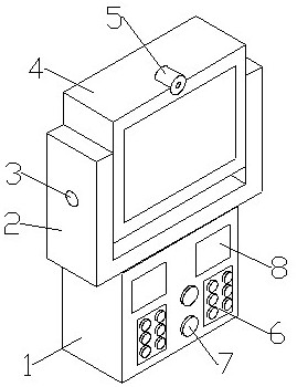
[0024] see Figure 1-4 , the present invention provides a technical solution: a bedside visual pager, including a box body 1, a U-shaped seat 2 is fixedly installed on the top of the box body 1, and the side plates on both sides of the U-shaped seat 2 are rotatably socketed with a rotating shaft 3 , display 4 is fixedly installed between 3 rotating shafts, camera 5 is fixedly installed on the top of display 4, pager extension processor and communication module...


PUM


Abstract

The invention discloses a bedside visual beeper and a visual calling system. The bedside visual beeper comprises a box body, a U-shaped seat is fixedly mounted at the top of the box body, rotating shafts are rotatably sleeved on side plates on two sides of the U-shaped seat, a display is fixedly mounted between the rotating shafts, a camera is fixedly mounted at the top of the display, and a beeper extension processor and a communication module are mounted in the box body. A button area, an intercom and a nameplate are installed on the outer wall of the box body, a beeper extension set is fixedly installed in the box body of the beeper, the management station host is connected with the beeper extension set through wireless signals, the beeper extension set is electrically connected with the button module, and the beeper extension set is electrically connected with the display module, the camera module and the intercom module. The management station host is connected with the nurse smart wristband and the nursing worker smart wristband and used for transmitting patient requirements to nurses and nursing workers, the nurses and the nursing workers can conveniently solve patient requests in time, information communication between the patients and the nurses and between the patients and the nursing workers is achieved, the patients can conveniently and directly express their own requirements, and the response time of the nurses and the nursing workers is prolonged.

Description

technical field [0001] The invention relates to the field of medical care technology, in particular to a bedside visual calling device and a visual calling system. Background technique [0002] As the number of patients in the hospital increases, people's demand for medical resources is gradually increasing. However, medical resources are limited. Therefore, nurses and nurses have become one of the busiest staff in the hospital. Nurses shuttle between wards, treatment rooms, Between various areas such as the office, the current ward call system is a centralized call. There is only one centralized button on the bedside of the patient, and the nurse or nurse in the nurse station is called through the button. The nurse and nurse need to go to the patient to listen to the patient's needs. It is a waste of time to prepare work supplies to meet the patient's needs, and when the nurse or nurse in charge of the patient's ward is away from the nurse's station, when going to the toile...

Claims


Application Information

Patent Timeline
IPC IPC(8): G08B3/10H04M11/02H04N7/14H04N7/18
Inventor 李雯颖
Owner 南京卫生高等职业技术学校
Learn More