SLAM loopback detection method based on mobile robot
A technology of mobile robots and detection methods, which is applied in the directions of instruments, measuring devices, surveying and mapping, and navigation, and can solve problems such as difficulty in ensuring global consistency.
- Summary
- Abstract
- Description
- Claims
- Application Information
AI Technical Summary
Problems solved by technology
Method used
Image
Examples
Embodiment 1
[0068] Embodiment 1: laser pretreatment
[0069] S101. Using the pre-integrated value of the IMU to remove the laser motion distortion caused by the robot motion;
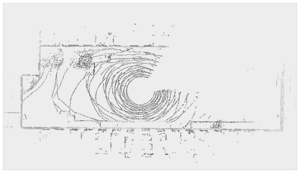
[0070] S102. A frame of laser point cloud data set is denoted as P={p 1 ,p 2 ,p 3 ,...,p n}, and projected onto the distance image;
[0071] S103, select a row of continuous points on the distance image, the set is denoted as R, point p i is the midpoint, p can be calculated by the following formula i The curvature value of :
[0072]
[0073] where d i for point p i Euclidean distance to lidar, set a value c b , when c is greater than c b is an edge point when c is less than c b is a plane point.
Embodiment 2
[0074] Example 2: Establishment of local subgraphs
[0075] S201. The relative attitude transformation of two consecutive frames, that is, the radar odometer is obtained by point-to-plane and point-to-edge scan matching methods, wherein the distance from the edge feature point to the line is calculated as follows:
[0076]
[0077] Point-to-surface calculations for planar features are as follows:
[0078]
[0079] Among them, and k+1 are continuous and associated two frames of laser light, i, j, l and m are the points in the two frames of laser light;
[0080] S202, using the LM nonlinear optimization method to obtain the pose transformation of two consecutive frames, that is, the radar odometer;
[0081] S203, select a key frame, set a distance value l and an angle value θ, when the distance of a certain frame is greater than l or the angle offset is greater than θ than the previous key frame, it will be selected as a key frame;
[0082] S204. The key frames form a lo...
Embodiment 3
[0083] Embodiment 3: Brand new descriptor, Edge-Planar Scan Context (EPSC) establishment
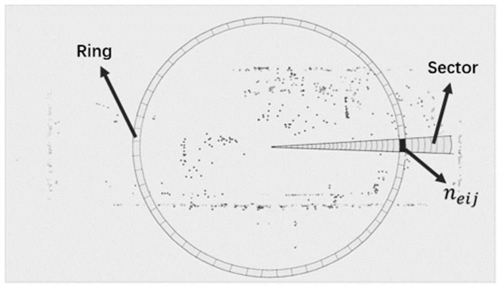
[0084] S301, extracting feature points, setting all point cloud sets of a local submap as S={s 1 ,s 2 ,...,s n}, and s k =(x k ,y k ,z k ), S e ={s e1 ,s e2 ,...,s em} and S p ={s p1 ,s p2 ,...,s p3} respectively represent the set of edge feature points and plane feature points in the sub-graph;
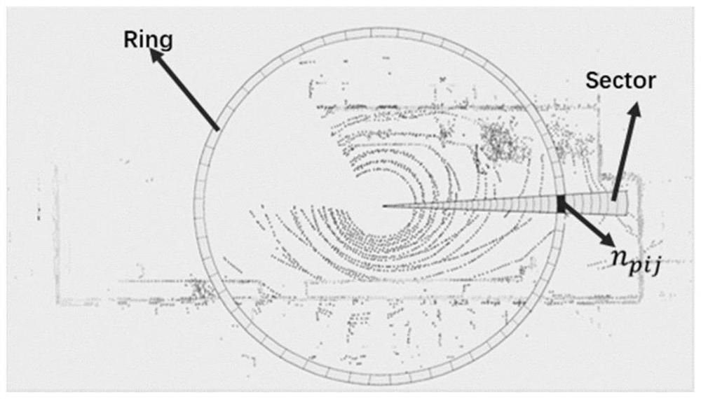
[0085] S302. Establish the sensor coordinate system, adopt the top view of the 3D scanned point cloud, and divide the ground area into multiple subspaces;
[0086] S303. The local subgraph is divided according to the azimuth and radial direction, and is divided into several rings, sectors, and subspaces with different colors, and each point s in the point cloud k can be expressed in polar coordinates:
[0087] the s k =[ρ k , θ k ,z k ]
[0088]
[0089]
[0090] Among them, the azimuth angle is specifically: from 0 to 2π in the lidar frame, and the radial direction i...
PUM
 Abstract
Description
Claims
Application Information
 - R&D
- Intellectual Property
- Life Sciences
- Materials
- Tech Scout
- Unparalleled Data Quality
- Higher Quality Content
- 60% Fewer Hallucinations
Browse by: Latest US Patents, China's latest patents, Technical Efficacy Thesaurus, Application Domain, Technology Topic, Popular Technical Reports.
© 2025 PatSnap. All rights reserved.Legal|Privacy policy|Modern Slavery Act Transparency Statement|Sitemap|About US| Contact US: help@patsnap.com


