Supporting formwork and construction method thereof

A formwork and beam technology, applied in the field of prefabricated cavity floor support formwork, can solve the problems of inconvenient adaptation adjustment, difficult matching adjustment, low construction efficiency, etc., and achieve obvious construction and economic benefits, and the structure is safe, reliable, and economical. The effect of the construction period

Pending Publication Date: 2021-04-16
HUBEI SYNTHETIC SPACE TECH CO LTD
View PDF0 Cites 0 Cited by
  • Summary
  • Abstract
  • Description
  • Claims
  • Application Information

AI Technical Summary

Problems solved by technology

On the other hand, during the construction of cast-in-place concrete, the workers stepped on and received uneven force, which caused subsidence and produced a large number of negative bending areas. At this time, it is necessary to adjust the support structure or strengthen the local structural strength accordingly. The existing construction technology is also suitable for this This kind of adaptive adjustment is extremely inconvenient, and time-consuming and laborious. Not only is it easy to cause congestion at the construction site, difficulty in matching adjustment, etc., but also the construction speed is slow, resulting in a long construction period and low construction efficiency.

Method used


Image

  • Supporting formwork and construction method thereof
  • Supporting formwork and construction method thereof
  • Supporting formwork and construction method thereof

Examples


Embodiment Construction

[0036] Embodiments of the present invention will be described in further detail below in conjunction with the accompanying drawings.

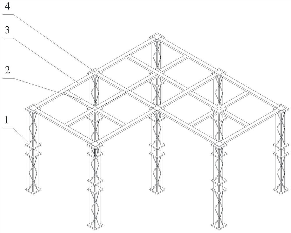
[0037] see figure 1 The schematic structural diagram of a supporting formwork in the illustrated embodiment of the present invention includes at least 2 crossbeams 2, at least 2 longitudinal beams 3, at least 4 connectors 4, and at least 4 columns 1, and the crossbeams 2 and longitudinal beams 3 pass through in turn The connectors 4 are connected to form a closed geometric plane, and one end of the column 1 is connected to the connectors 4 respectively.

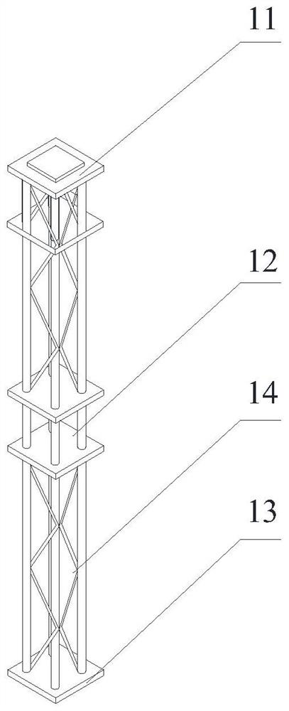
[0038] Among them, see figure 2 It is a schematic structural view of the column in the embodiment of the present invention. The column 1 is provided with a top plate 11, a bottom plate 13 and a force column 14. The top plate 11 is used as a platform for connecting the connector 4 to be provided with corresponding fixing bolts or buckles. The top plate 11 and the bottom plate 13 There is a r...


PUM


Abstract

The invention discloses a supporting formwork and a construction method thereof, and relates to the technical field of fabricated cavity floor supporting formworks. The supporting formwork comprises at least two cross beams, at least two longitudinal beams, at least four connecting pieces and at least four stand columns, the cross beams and the longitudinal beams are sequentially connected through the connecting pieces to form a closed geometric plane, and one ends of the stand columns are correspondingly connected with the connecting pieces; the stand columns are provided with top plates, bottom plates and stress columns, and adjusting valves are arranged between the top plates and the bottom plates; and the connecting pieces are provided with at least two sockets and at least one column interface, the sockets are correspondingly connected with the cross beams and the longitudinal beams, and the column interfaces are connected with the stand columns. According to the supporting formwork, building construction of the supporting formwork can be eliminated, the number of formwork supports is reduced, the construction period is shortened, and cost is effectively reduced.

Description

technical field [0001] The invention relates to the technical field of an assembled cavity floor support formwork, in particular to a support formwork and a construction method thereof. Background technique [0002] At present, in the construction of prefabricated buildings, the construction involving prefabricated cavity floors is often partly prefabricated and partly cast-in-place. That is to say, a whole floor slab is formed by paving the prefabricated cavity first, and pouring concrete again. However, this construction method needs to support a large number of formworks at the bottom to support the weight of the cavity formwork and the cavity. However, under the existing construction technology, due to the dense placement of too many support frames, the space environment of the construction site is greatly limited. During the construction period, the tools and materials on site cannot be placed and are disorderly and disorderly, making it difficult for personnel to trav...

Claims


Application Information

Patent Timeline
Patent Type & Authority Applications(China)
IPC IPC(8): E04G11/48E04G21/00
Inventor 傅礼铭
Owner HUBEI SYNTHETIC SPACE TECH CO LTD
Why Eureka
Try Eureka