
Unmanned aerial vehicle automatic battery replacing system

A technology of unmanned aerial vehicles and electrical systems, applied in the field of unmanned aerial vehicles, can solve the problems of unmanned aerial vehicles such as damage to core components, frequent take-offs and landings, complex application environments, etc., and achieve the effect of promoting perfection and reducing difficulty

Pending Publication Date: 2021-04-16
SHANGHAI FIRE RES INST OF MEM +1
View PDF0 Cites 3 Cited by
  • Summary
  • Abstract
  • Description
  • Claims
  • Application Information

AI Technical Summary

Problems solved by technology

[0003] However, UAVs that are hoverable, flexible, and economical also have serious shortcomings in practical applications, especially in firefighting applications.
Due to the limitation of battery storage power, the effective flight time of drones is quite limited when performing various firefighting tasks, resulting in frequent take-offs and landings that are extremely difficult to operate and labor-intensive battery replacements
At the same time, the application environment of fire-fighting drones is complex. When taking off and landing in rugged and dusty areas, the debris and sand rolled up by the propellers will damage the core components of the drone.
Therefore, the take-off and landing of drones has high requirements on ground conditions, which undoubtedly makes the take-off and landing process time-consuming and risky
To a considerable extent, it affects the efficiency of task execution and limits the ability of drones to perform tasks in the context of firefighting

Method used


Image

  • Unmanned aerial vehicle automatic battery replacing system
  • Unmanned aerial vehicle automatic battery replacing system
  • Unmanned aerial vehicle automatic battery replacing system

Examples


Embodiment Construction

[0026] In order to make the technical means, creative features, goals and effects achieved by the present invention easy to understand, the present invention will be further described below in conjunction with specific illustrations.

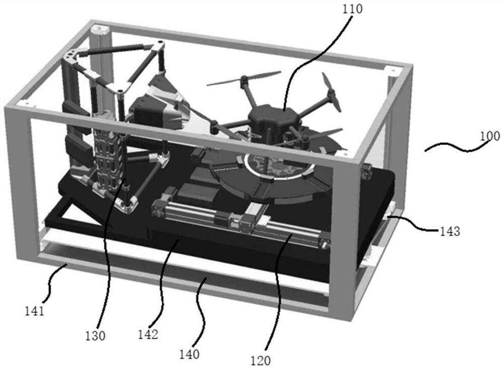
[0027] Aiming at the working characteristics of fire-fighting drones, this example presents a UAV automatic battery replacement system solution, which enables fire-fighting drones to complete automatic take-off and landing on the roof of a fire truck far away from the ground, autonomously Work, automatic battery replacement, and no manual intervention in the whole process, with a mission platform for logistical support.

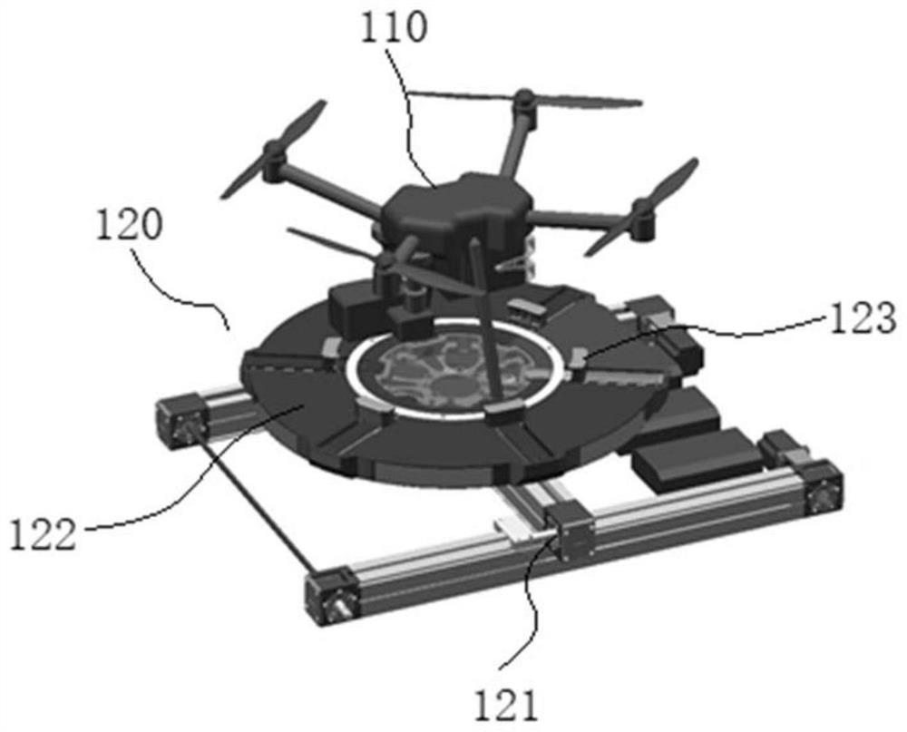
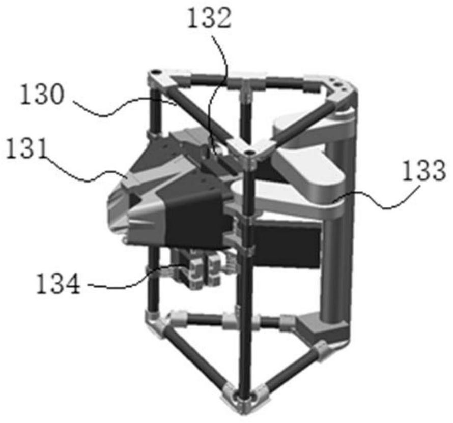
[0028] see figure 1 , which shows an example of the composition of the UAV automatic battery replacement system given in this example. It can be seen from the figure that the UAV automatic power exchange system 100 mainly includes a general-purpose UAV 110 , a UAV take-off and landing platform 120 , a UAV power exchange platfo...


PUM


Abstract

The invention discloses an unmanned aerial vehicle automatic battery replacing system which comprises a general unmanned aerial vehicle, an unmanned aerial vehicle take-off and landing platform, an unmanned aerial vehicle battery replacement platform and a lifting mechanism. The unmanned aerial vehicle take-off and landing platform guides the general unmanned aerial vehicle to take off and land and automatically tracks and locks the general unmanned aerial vehicle in the landing process of the general unmanned aerial vehicle; the unmanned aerial vehicle battery replacement platform is used for docking the general unmanned aerial vehicle landing on the unmanned aerial vehicle take-off and landing platform and completing battery replacement after docking; and the lifting mechanism can integrally lift and / or rotate the unmanned aerial vehicle take-off and landing platform to the take-off position and / or angle of the universal unmanned aerial vehicle. The unmanned aerial vehicle automatic battery replacing system provided by the invention can realize autonomous take-off and landing and battery replacement of the unmanned aerial vehicle so as to safely, quickly and efficiently realize long-time autonomous endurance with a task load of the fire-fighting unmanned aerial vehicle. Therefore, the operation difficulty of the unmanned aerial vehicle is reduced to a great extent.

Description

technical field [0001] The invention relates to unmanned aerial vehicle technology, in particular to automatic battery replacement technology for unmanned aerial vehicles. Background technique [0002] With the rapid development of drone technology, its use in various fields is increasing day by day. From military to civilian, from power line inspection to emergency rescue. Unmanned aerial vehicles continue to emerge and play an increasingly important role. [0003] However, UAVs that are hoverable, flexible, and economical also have serious shortcomings in practical applications, especially in firefighting applications. Due to the limitation of battery storage power, the effective flight time of drones is quite limited when performing various firefighting tasks. The result is frequent take-offs and landings that are extremely difficult to operate and labor-intensive battery replacements. At the same time, the application environment of fire-fighting drones is complex. Wh...

Claims


Application Information

Patent Timeline
Patent Type & Authority Applications(China)
IPC IPC(8): B60L53/80B64F1/00
CPCY02T10/70Y02T10/7072
Inventor 李睿堃朱青钟帅
Owner SHANGHAI FIRE RES INST OF MEM
Learn More