
Auxiliary positioning mechanism for industrial welding machine

An auxiliary positioning and welding mechanism technology, applied in welding/cutting auxiliary equipment, auxiliary devices, welding equipment, etc., can solve the problems of welding position offset, sliding is not flexible enough, poor positioning effect, etc., to achieve diverse positioning and structural composition Simple, structured effect

Pending Publication Date: 2021-04-16
ZHEJIANG UNIVERSITY OF SCIENCE AND TECHNOLOGY
View PDF7 Cites 0 Cited by
  • Summary
  • Abstract
  • Description
  • Claims
  • Application Information

AI Technical Summary

Problems solved by technology

[0002] Welding is a method often used in mechanical processing or construction in industrial production. In the process of mechanical processing or construction, the positioning accuracy of welding is an important indicator in welding. At this stage, welding butt joints mostly use manual butt joints. , and the manual positioning method is not only cumbersome to operate, but also prone to welding position deviation, and the butt joint efficiency is low. However, when the existing industrial welding machine welds the workpiece, it mostly uses the linear guide rail positioning method for positioning. This method can target the plane. Higher positioning, but this method is not flexible enough to slide when positioning, and the positioning effect on curved surfaces and slopes is not good. In view of this, in-depth research on the above problems led to this case.

Method used


Image

  • Auxiliary positioning mechanism for industrial welding machine
  • Auxiliary positioning mechanism for industrial welding machine
  • Auxiliary positioning mechanism for industrial welding machine

Examples


Embodiment

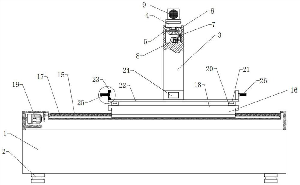
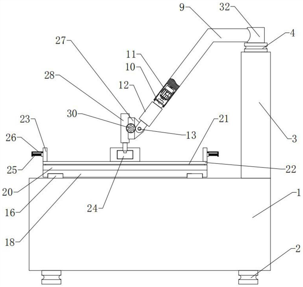
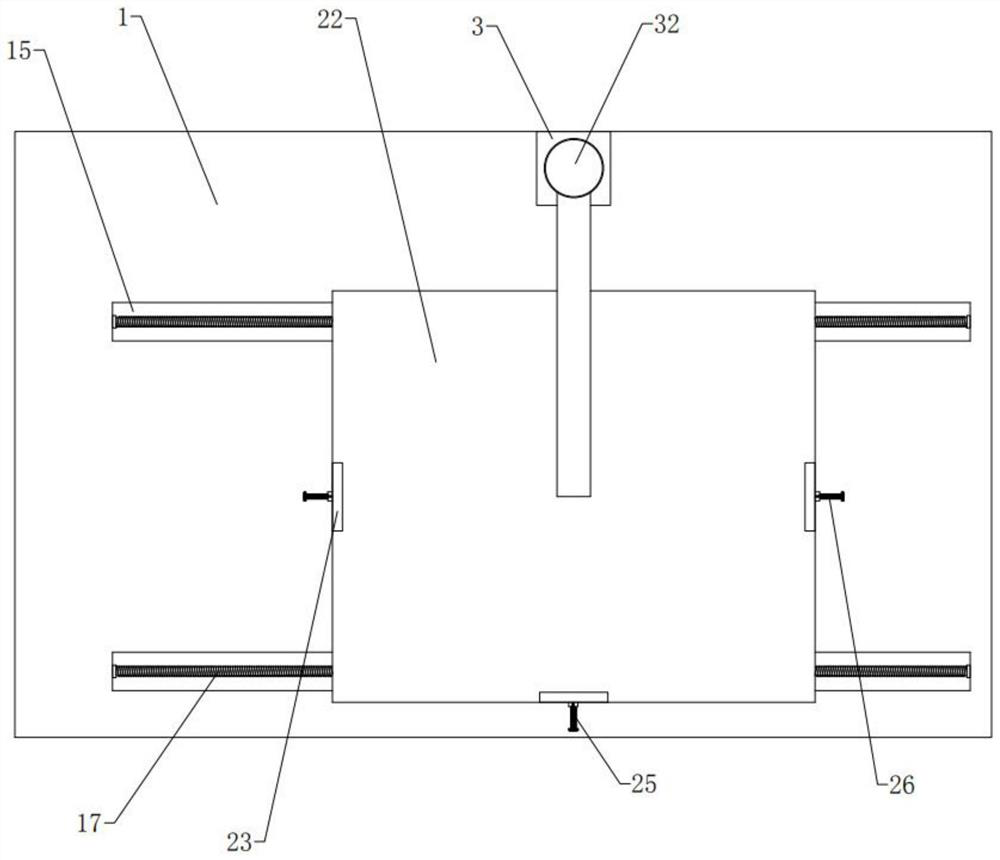
[0031] Embodiment: according to specification Figure 1-6 It can be seen that this case is an auxiliary positioning mechanism for industrial welding machines, including a mounting base 1, two pairs of legs 2 and a support frame 3, two pairs of legs 2 are provided on the bottom surface of the mounting base 1, and a support frame is provided on the top side of the mounting base 1 3. The support frame 3 is provided with a welding mechanism, and a steering movable structure is provided between the support frame 3 and the welding mechanism. The sliding structure and the fixed structure installed on the planar sliding structure, in the specific implementation process, the installation base 1 is supported by the bracket to raise the overall height of the equipment, the support frame 3 is a steel frame with a columnar structure, and the support frame 3 Support the welding mechanism and the steering movable structure, the steering movable structure fixes the welding mechanism, realizes...


PUM


Abstract

The invention discloses an auxiliary positioning mechanism for an industrial welding machine. The mechanism comprises a mounting base, two pairs of supporting legs and a supporting frame, the two pairs of supporting legs are arranged on the bottom face of the mounting base, the supporting frame is arranged on one side of the top face of the mounting base, a welding mechanism is arranged on the supporting frame, and a steering movable structure is arranged between the supporting frame and the welding mechanism. A plane shaft sliding positioning mechanism is arranged on the mounting base. The auxiliary positioning mechanism for the industrial welding machine has the beneficial effects that the auxiliary positioning mechanism is simple in structure and convenient to operate, horizontal adjustment of materials is achieved through a plane sliding structure, then horizontal positioning of the materials can be achieved, as for curved-surface materials, the angle of the welding mechanism is adjusted through the steering movable structure, flexible positioning in curved surfaces can be achieved, the overall structural composition is simple, automatic positioning is adopted, the precision is high, positioning can be conducted on the horizontal plane, and the positioning functions of the curved surfaces can be diversified.

Description

technical field [0001] The invention relates to the technical field of industrial welding, in particular to an auxiliary positioning mechanism for an industrial welding machine. Background technique [0002] Welding is a method often used in mechanical processing or construction in industrial production. In the process of mechanical processing or construction, the positioning accuracy of welding is an important indicator in welding. At this stage, welding butt joints mostly use manual butt joints. , and the manual positioning method is not only cumbersome to operate, but also prone to welding position deviation, and the butt joint efficiency is low. However, when the existing industrial welding machine welds the workpiece, it mostly uses the linear guide rail positioning method for positioning. This method can target the plane. Higher positioning, but this method is not flexible enough to slide when positioning, and the positioning effect on curved surfaces and slopes is not...

Claims


Application Information

Patent Timeline
Patent Type & Authority Applications(China)
IPC IPC(8): B23K37/02B23K37/04
Inventor 张敬强
Owner ZHEJIANG UNIVERSITY OF SCIENCE AND TECHNOLOGY
Learn More