Cable laying frame for mining machinery and using method thereof
A cable laying and mechanical technology, applied in cable laying equipment, cable installation, ground cable installation, etc., can solve the problems of poor safety, scattered cables, high humidity, etc., to save handling and installation time, prolong service life, good creative effect
- Summary
- Abstract
- Description
- Claims
- Application Information
AI Technical Summary
Problems solved by technology
Method used
Image
Examples
Embodiment 1
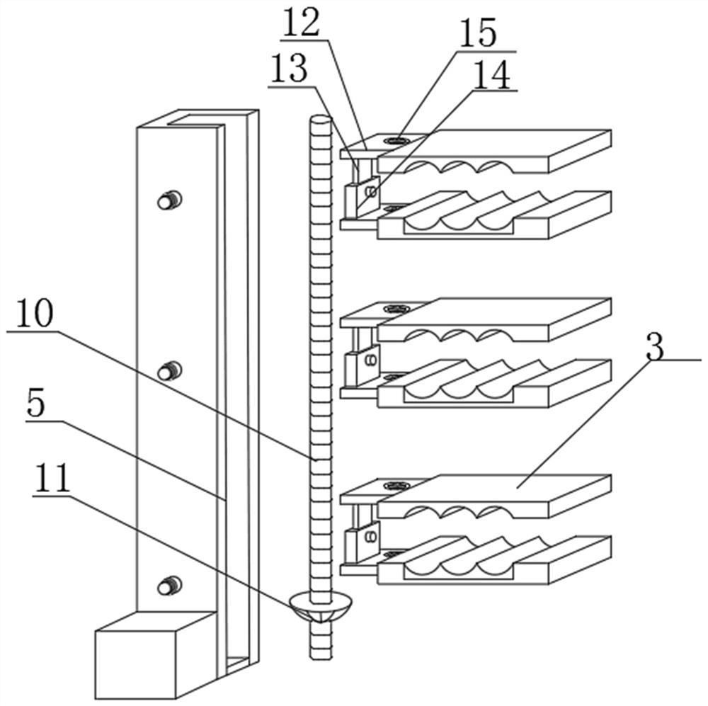
[0035] Such as Figure 1-8 As shown, a cable laying frame for mining machinery and its use method, including No. 1 support frame (1) and No. 2 support frame (2) fixedly installed on the inner edge of the mine roadway, and No. The No. 1 support frame (2) is arranged crosswise, the outer surface of the No. 1 support frame (1) is slidingly connected with the upper splint (3) and the lower splint (4), and the No. 1 support frame (1) and the No. 2 support frame (2) The drive motor (7) is fixedly installed on the sides, the side of the lower splint (4) facing the upper splint (3) is fixed with a flexible pad (6), and the inside of the No. 1 support frame (1) is provided with a sliding groove ( 5), the sliding groove (5) is internally rotated with a rotating rod (25), the upper end of the sliding groove (5) is connected to the upper opening of the roadway, and the upper end of the rotating rod (25) is fixedly installed with a No. 1 threaded rod (10), A No. 1 bevel gear (11) is fixed...
Embodiment 2
[0046] Such as Figure 1-8 As shown, a cable laying frame for mining machinery includes No. 1 support frame (1) and No. 2 support frame (2) fixedly installed on the inner edge of the mine roadway, No. 1 support frame (1) and No. 2 support frame ( 2) Cross setting, the outer surface of No. 1 support frame (1) is slidingly connected with upper splint (3) and lower splint (4), and the sides of No. 1 support frame (1) and No. 2 support frame (2) are fixedly installed There is a drive motor (7), a flexible pad (6) is fixedly installed on the side of the lower splint (4) facing the upper splint (3), and a sliding groove (5) is opened inside the No. 1 support frame (1), sliding The groove (5) is internally rotated with a rotating rod (25), the upper end of the sliding groove (5) is connected to the upper opening of the roadway, the upper end of the rotating rod (25) is fixedly installed with a No. 1 threaded rod (10), and the rotating rod (25 ) is fixedly installed on the outer surf...
PUM
 Abstract
Description
Claims
Application Information
 - R&D Engineer
- R&D Manager
- IP Professional
- Industry Leading Data Capabilities
- Powerful AI technology
- Patent DNA Extraction
Browse by: Latest US Patents, China's latest patents, Technical Efficacy Thesaurus, Application Domain, Technology Topic, Popular Technical Reports.
© 2024 PatSnap. All rights reserved.Legal|Privacy policy|Modern Slavery Act Transparency Statement|Sitemap|About US| Contact US: help@patsnap.com


