
Sealed wiring terminal and compressor

A terminal and wiring hole technology, which is applied to contact parts, mechanical equipment, machines/engines, etc., can solve problems such as airtight failure, airtight sealing failure, and insufficient compression resistance of wiring holes.

Pending Publication Date: 2021-04-13
CHAOZHOU THREE CIRCLE GRP
View PDF0 Cites 0 Cited by
  • Summary
  • Abstract
  • Description
  • Claims
  • Application Information

AI Technical Summary

Problems solved by technology

[0003] As the core wiring part of the compressor, the sealed terminal is in repeated high and low pressure conditions for a long time, and glass, as a brittle material, is very sensitive to external tensile stress. Defects such as cracks and chipping in the glass may even lead to safety accidents such as airtight sealing failure and steel needle flying out
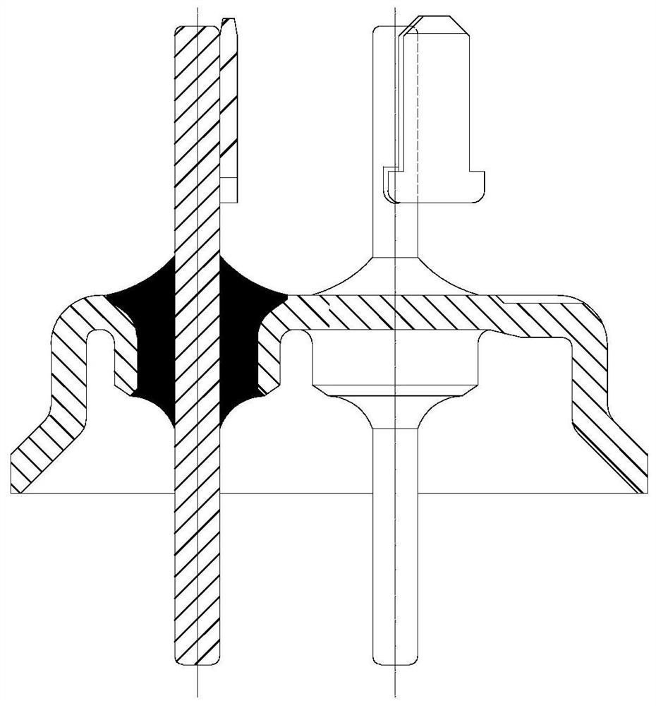
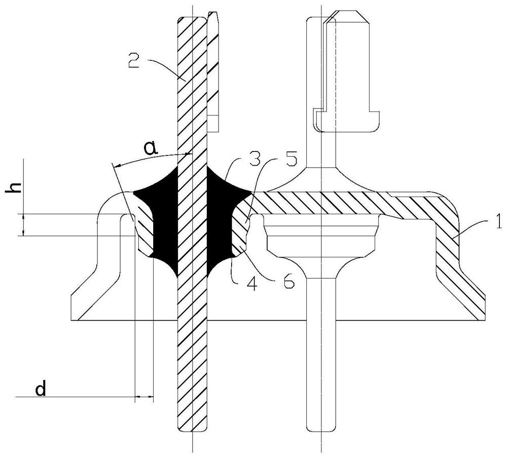
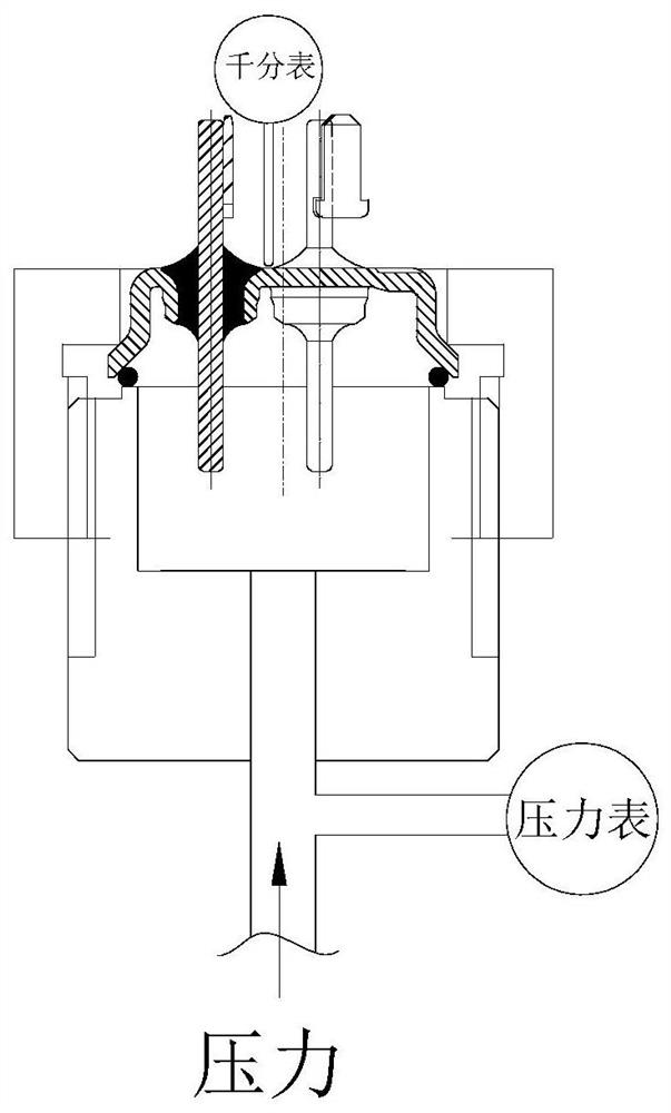
[0004] Due to the small wall thickness of the wiring hole in the existing end cover structure, when the internal pressure deformation of the terminal bulges, the compression resistance of the wiring hole is insufficient and large deformation occurs at the same time, which causes serious damage to the glass inside the wiring hole, and eventually airtight failure or Safety issues such as steel needle flying out

Method used


Image

  • Sealed wiring terminal and compressor
  • Sealed wiring terminal and compressor
  • Sealed wiring terminal and compressor

Examples


Embodiment Construction

[0025] This part will describe the specific embodiment of the present invention in detail, and the preferred embodiment of the present invention is shown in the accompanying drawings. Each technical feature and overall technical solution of the invention, but it should not be understood as a limitation on the protection scope of the present invention.

[0026] In the present invention, if there is a description of directions (up, down, left, right, front and back), it is only for the convenience of describing the technical solution of the present invention, rather than indicating or implying that the referred technical features must have specific Orientation, construction and operation in a particular orientation, therefore should not be construed as limiting the invention.

[0027] In the present invention, "several" means one or more, "multiple" means more than two, "greater than", "less than", "exceeding", etc. are understood as excluding the original number; "above", "belo...


PUM

PropertyMeasurementUnit
Wall thicknessaaaaaaaaaa
Heightaaaaaaaaaa

Abstract

The invention discloses a sealed wiring terminal and a compressor. The sealed wiring terminal comprises an end cover which has a wiring hole, and a binding post, wherein the hole wall of the wiring hole extends to the inner side of the end cover, the outer wall surface of the hole wall of the wiring hole is in a step shape, the hole wall of the wiring hole forms a plurality of segments with different thicknesses through the step surface, and the wall thicknesses of the plurality of sections are decreased progressively along the extension direction of the hole wall of the wiring hole; and the binding post penetrates through the wiring hole and is limited in the wiring hole through insulating glass. According to the sealed wiring terminal, the steps are arranged at the bottom part of the wiring hole, so that the thickness of the hole wall is increased, the length of the wiring hole is not greatly changed, the deformation resistance of the wiring hole is effectively improved, and the reliability of the terminal is improved.

Description

technical field [0001] The invention is used in the field of connection terminals, and in particular relates to a sealed connection terminal and a compressor. Background technique [0002] Sealed terminals are widely used in compressor components and are indispensable key components in compressors. At present, conventional terminal blocks include end caps, terminal posts, and glass fusion parts that seal the end caps and terminal posts, such as figure 1 As shown, the outer wall of the wiring hole of the end cover is a straight line structure and is perpendicular to the inner surface of the end cover. [0003] As the core wiring part of the compressor, the sealed terminal is in repeated high and low pressure conditions for a long time, and glass, as a brittle material, is very sensitive to external tensile stress. Defects such as cracks and chipping in the glass may even lead to safety accidents such as airtight sealing failure and steel needle flying out. [0004] Due to ...

Claims


Application Information

Patent Timeline
IPC IPC(8): H01R13/02F04B39/00
CPCH01R13/02F04B39/00
Inventor 郑镇宏
Owner CHAOZHOU THREE CIRCLE GRP
Learn More