
Flow-limiting revolving door

A technology of revolving doors and rotating shafts, which is applied in the direction of turnstiles, windows/doors, building components, etc., and can solve the problems of gates not being able to pass through frequency restrictions, etc.

Active Publication Date: 2021-04-13
山东欧盾门业有限公司
View PDF6 Cites 9 Cited by
  • Summary
  • Abstract
  • Description
  • Claims
  • Application Information

AI Technical Summary

Problems solved by technology

[0003] In view of the above situation, in order to overcome the defects of the prior art, the present invention provides a current-limiting revolving door, which effectively solves the problem that the gate cannot limit the passing frequency

Method used


Image

  • Flow-limiting revolving door
  • Flow-limiting revolving door
  • Flow-limiting revolving door

Examples


Embodiment Construction

[0022] The specific implementation manners of the present invention will be described in further detail below in conjunction with the accompanying drawings.

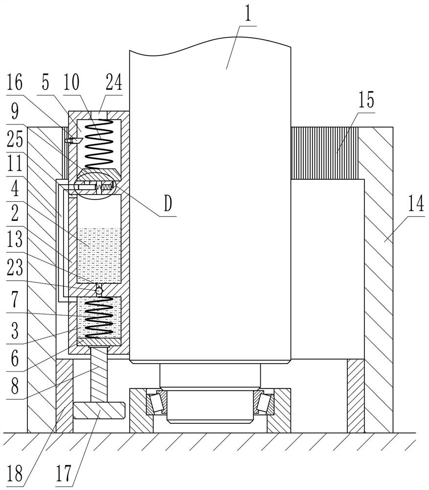
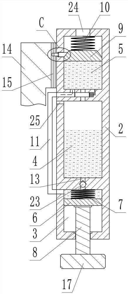
[0023] Depend on Figure 1 to Figure 10 Given, the present invention includes the rotating shaft 1 of the turnstile, on the outer wall of the rotating shaft 1 is fixed a columnar housing 2 parallel to it, and the housing 2 is divided into a first chamber 3, a second chamber 4 and a chamber from bottom to top. The third chamber 5, the first chamber 3 and the second chamber 4 are filled with liquid, the first piston 6 is installed in the first chamber 3, the first compression spring 7 is installed on the upper end of the first piston 6, and the lower end is fixed with a A push rod 8 protruding from the housing 2, a second piston 9 is installed in the third chamber 5, a second compression spring 10 is installed on the upper end of the second piston 9, the first chamber 3 and the third chamber 5 A liquid pipe 11 is connecte...


PUM


Abstract

The invention relates to a flow-limiting revolving door. The flow-limiting revolving door effectively solves the problem that a gate cannot limit the passing frequency. According to the technical scheme, the flow-limiting revolving door comprises a rotating shaft of the gate, a shell parallel to the rotating shaft is fixed to the outer wall of the rotating shaft, the interior of the shell is divided into a first cavity, a second cavity and a third cavity from bottom to top, a piston is installed in the third cavity, the rotating shaft rotates to enable the first cavity to suck liquid from the second cavity and then push the liquid in the first cavity into the third cavity, a first through hole is formed in the lower end of the third cavity, a fixed annular sleeve is coaxially arranged outside the rotating shaft, teeth are evenly distributed on the circumference of the inner wall of the annular sleeve, a clamping block penetrating through the side wall of the third cavity in the radial direction is installed on the third cavity, if the rotating shaft rotates too fast, the liquid can enter the third cavity too fast, the clamping block can be pushed outwards after the piston moves upwards to exceed the highest position, and the outer end of the clamping block is inserted into the teeth of the annular sleeve; and according to the flow-limiting revolving door, the passing frequency of the gate can be limited, and people in places in the gate can be prevented from being gathered and disordered.

Description

technical field [0001] The invention relates to the field of traffic equipment, in particular to a current-limiting revolving door. Background technique [0002] The gate is a device that restricts traffic, and is widely used at the entrances and exits of airports, stations, communities, etc. The function of the gate is to limit the number of people passing each time, to avoid multiple people passing at the same time, to avoid crowding, and to facilitate ticket checks, security checks, etc. The work is carried out smoothly and orderly; the current gates only limit the number of people passing each time to achieve a single pass, but cannot limit the frequency of passing, which will cause the ticket check, security check or other work for the previous person to not be completed. The latter person has already entered the site through the gate, causing congestion in the site and confusion in related work places, which is prone to omission of personnel such as missed inspections;...

Claims


Application Information

Patent Timeline
IPC IPC(8): E06B11/08
CPCE06B11/08E06B11/085Y02E10/20
Inventor 李想
Owner 山东欧盾门业有限公司
Learn More