Cloth printing device for cloth production
A cloth and printing technology, which is applied in the field of cloth printing devices for cloth production, can solve problems such as low efficiency, unsafe, complicated operation, etc.
- Summary
- Abstract
- Description
- Claims
- Application Information
AI Technical Summary
Problems solved by technology
Method used
Image
Examples
Embodiment 1
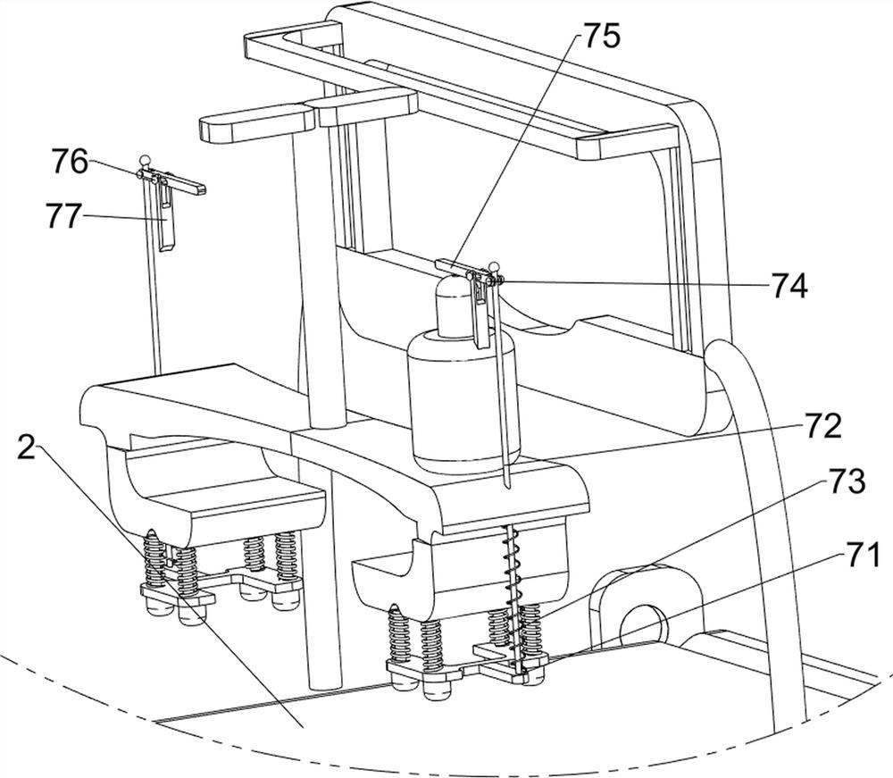
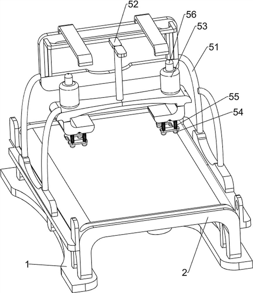
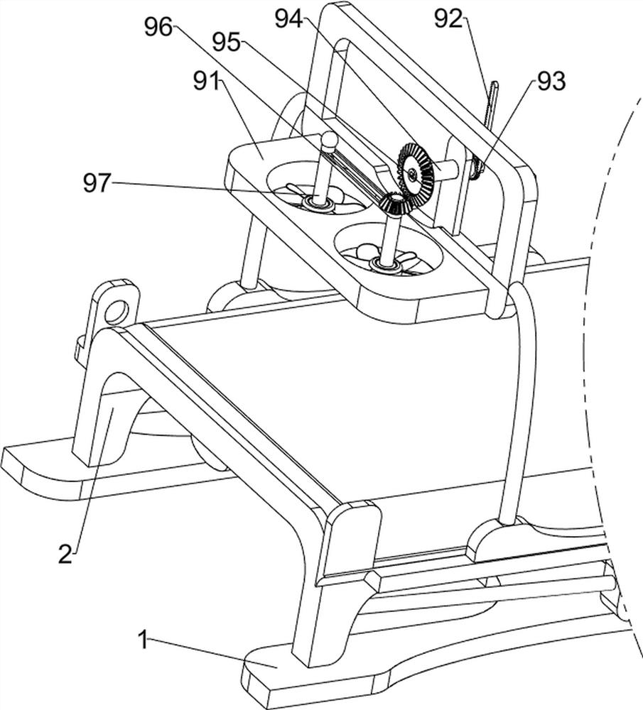
[0082] A cloth printing device for cloth production, such as figure 1 As shown, it includes a base 1, a first fixed frame 2, a first fixed block 3, a rotating mechanism 4 and a printing mechanism 5. The base 1 is provided with a first fixed frame 2, and the left and right sides of the first fixed frame 2 are provided with The first fixed block 3 is provided with a rotating mechanism 4 at the upper rear of the base 1, and the rotating mechanism 4 is connected with the first fixed frame 2 and the first fixed block 3, and the first fixed block 3 is provided with a printing mechanism 5.
[0083] When people need to print the cloth, first people put the cloth on the top of the first fixed frame 2, and clamp one end of the cloth in the rotating mechanism 4, then people make the rotating mechanism 4 run, and the rotating mechanism 4 makes the cloth move backward intermittently , whenever the cloth stops moving, people make the printing mechanism 5 run, and the printing mechanism 5 pr...
Embodiment 2
[0085] On the basis of Example 1, such as figure 2 with image 3 As shown, the rotating mechanism 4 includes a second fixed block 41, a motor 42, a half gear 43, a first rotating shaft 44, a first gear 45, a second rotating shaft 46, a first sliding sleeve 47, a first sliding rod 48, a first Spring 49, the third rotating shaft 410 and the fourth rotating shaft 411, a second fixed block 41 is provided on the left side of the upper rear part of the base 1, the second fixed block 41 is connected with the first fixed frame 2, and a motor is installed on the top of the second fixed block 41 42, the output shaft of the motor 42 is provided with a half gear 43, the first rotating shaft 44 is rotationally connected between the first fixed block 3 rear parts on the left and right sides, and the first rotating shaft 44 is rotationally connected with the first fixed frame 2, First sliding sleeves 47 are arranged on the left and right sides of the upper rear part of the base 1, and the ...
Embodiment 3
[0090] On the basis of Example 2, such as figure 1 , Figure 4 , Figure 5 , Image 6 with Figure 7 As shown, an automatic pressing mechanism 6 is also included, and the automatic pressing mechanism 6 includes a second gear 61, a fifth rotating shaft 62, a first transmission assembly 63, a sixth rotating shaft 64, a first bevel gear set 65, a third fixed Block 66, the seventh rotating shaft 67, the second transmission assembly 68, the space cam 69, the fourth fixed block 610, the first connecting rod 611 and the third spring 612, the left side of the first fixed block 3 left rear rotating There is a fifth rotating shaft 62, the left side of the fifth rotating shaft 62 is provided with a second gear 61, the second gear 61 meshes with the half gear 43, and the first fixed block 3 top side front part on the left side is provided with a third fixed block 66, The third fixed block 66 is provided with a sixth rotating shaft 64 in the left rotating type, and the first transmissi...
PUM
 Abstract
Description
Claims
Application Information
 - Generate Ideas
- Intellectual Property
- Life Sciences
- Materials
- Tech Scout
- Unparalleled Data Quality
- Higher Quality Content
- 60% Fewer Hallucinations
Browse by: Latest US Patents, China's latest patents, Technical Efficacy Thesaurus, Application Domain, Technology Topic, Popular Technical Reports.
© 2025 PatSnap. All rights reserved.Legal|Privacy policy|Modern Slavery Act Transparency Statement|Sitemap|About US| Contact US: help@patsnap.com


