Shunting type cooling fan

A cooling fan and shunt-type technology, applied in the field of shunt-type cooling fans, can solve the problems of reducing fan outlet pressure, increasing air flow resistance, increasing energy consumption, etc., to reduce airflow vortices, balance negative pressure areas, and reduce aerodynamic noise and the effect of vibration noise

Pending Publication Date: 2021-04-09
太仓欣华盈电子有限公司
View PDF0 Cites 4 Cited by
  • Summary
  • Abstract
  • Description
  • Claims
  • Application Information

AI Technical Summary

Problems solved by technology

[0002] Fans are used in many electronic products. The airflow generated by the fan takes away the heat generated by the electronic components, so as to ensure the normal operation of the electronic products. Generally, the flow channels of cooling fans are designed to be circular or several phases in the market. The cut arc is very random in design. This unreasonable arc size will increase the resistance of air flow, reduce the air pressure of the fan, and increase energy consumption.

Method used


Image

  • Shunting type cooling fan
  • Shunting type cooling fan
  • Shunting type cooling fan

Examples


Embodiment Construction

[0022] The present invention will be described in detail below in conjunction with various embodiments shown in the drawings. However, these embodiments do not limit the present invention, and structural, method, or functional changes made by those skilled in the art according to these embodiments are included in the protection scope of the present invention.

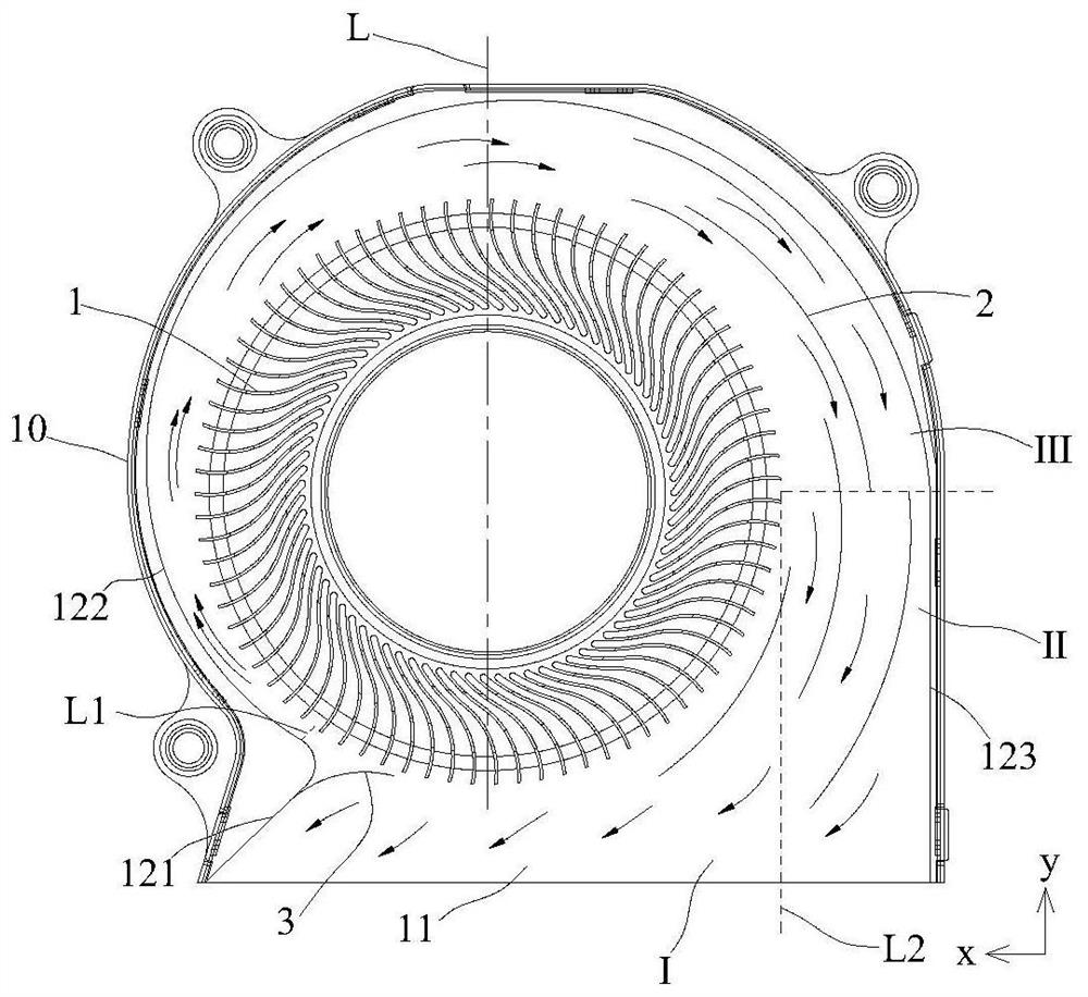
[0023] The invention discloses a split-flow cooling fan, which comprises a frame and a fan wheel accommodated in the frame. The fan wheel has a center line of the fan wheel arranged along a first direction, and an air outlet is formed on one side of the frame. A flow channel is formed on the periphery of the wheel, and a plurality of guide vanes for evenly dividing the air flow are installed in the flow channel along the direction of air flow.

[0024] The present invention will be further described below in conjunction with specific examples.

[0025] ginseng figure 1 As shown, a split-type heat dissipation fan inclu...


PUM


Abstract

The invention discloses a shunting type cooling fan. The shunting type cooling fan comprises a frame body and a fan wheel contained in the frame body; the fan wheel is provided with a fan wheel center line arranged in the first direction; an air outlet is formed in one side of the frame body; a flow channel is formed in the frame body and located on the periphery of the fan wheel; and a plurality of flow deflectors used for evenly distributing air flow are installed in the flow channel in the advancing direction of the air flow. the flow deflectors are mounted in the flow channel, so that gas in the flow channel flows more uniformly; airflow vortexes are reduced; aerodynamic noise and vibration noise are reduced; a negative pressure area is balanced; and a larger actual air inlet area is guaranteed.

Description

technical field [0001] The invention belongs to the field of fans, and in particular relates to a split-flow cooling fan. Background technique [0002] Fans are needed in many electronic products. The airflow generated by the fan takes away the heat generated by the electronic components, so as to ensure the normal operation of the electronic products. Generally, the flow channels of cooling fans are designed to be circular or several phases in the market. The cut arc is very random in design. This unreasonable arc size will increase the resistance of air flow, reduce the air outlet pressure of the fan, and increase energy consumption. [0003] Therefore, in view of the above technical problems, it is necessary to provide a split flow cooling fan. Contents of the invention [0004] In view of this, the object of the present invention is to provide a split-flow heat dissipation fan to reduce energy consumption to the greatest extent. [0005] In order to achieve the above...

Claims


Application Information

Patent Timeline
Patent Type & Authority Applications(China)
IPC IPC(8): F04D25/08F04D29/42F04D29/44F04D29/66
CPCF04D25/08F04D29/422F04D29/4226F04D29/444F04D29/667
Inventor 雷淑雅任晓英
Owner 太仓欣华盈电子有限公司
Why Eureka
Try Eureka