Rainwater mud settling trap

A sludge well and rainwater technology, applied in water/sludge/sewage treatment, sedimentation tank, sedimentation separation, etc., can solve the problems of large rainwater flow, poor sludge effect, and high cleaning cost, and achieve high safety and structure. Simple, construction-friendly effect

Pending Publication Date: 2021-04-09
北京北排水务设计研究院有限公司
View PDF0 Cites 0 Cited by
  • Summary
  • Abstract
  • Description
  • Claims
  • Application Information

AI Technical Summary

Problems solved by technology

[0002] At present, there are few facilities for initial rainwater treatment, and most of the rainwater regulation and storage facilities in the community are used to discard the initial rainwater. A 60cm deep sedimentation tank is installed at the bottom of the inspection well for regular dredging of the sediment. This method has two disadvantages when applied to the rainwater pipeline system: 1. The deposited silt is not easy to clear out, and the cleaning cost is high. After the first rainfall, the sedimentation tank It is full of rainwater and silt, if it is not cleared in time, the rainwater will pass through the upper part of the sedimentation tank during the next rainfall, forming a short flow, without effective residence time, and the sedimentation effect is poor; 2. In case of heavy rainfall, the rainwater flow in the rainwater pipe will Large, high flow rate of rainwater, the pollutants deposited in the sedimentation tank are easy to be washed up again and enter the downstream water body with rainwater

Method used


Image

  • Rainwater mud settling trap
  • Rainwater mud settling trap
  • Rainwater mud settling trap

Examples


Embodiment

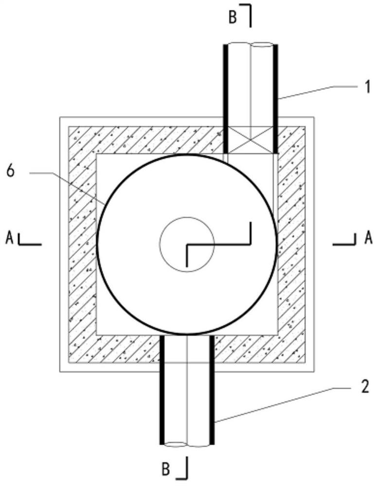
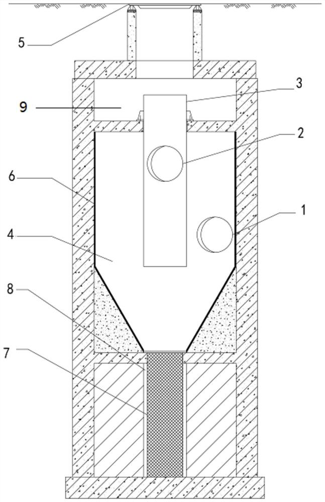
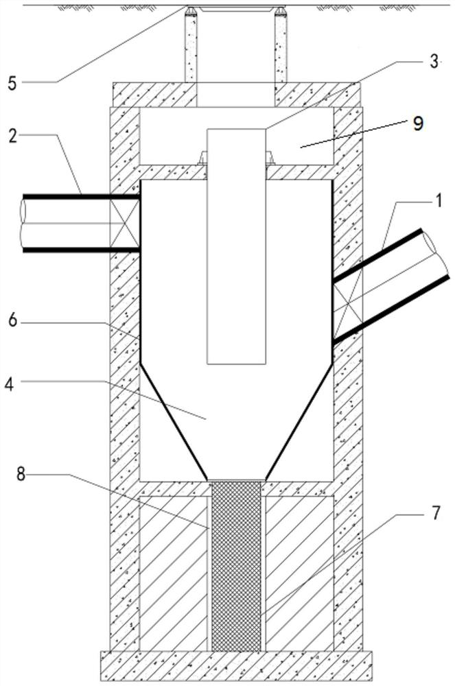
[0056] Such as Figure 1 to Figure 3 As shown, the present invention provides a kind of rainwater sedimentation well, comprising:

[0057] The sand-water separation well chamber 4, the sand-water separation well chamber 4 includes a first part and a second part, the first part is straight cylindrical, the second part is conical, and the second part is located on the lower side of the first part;

[0058] The water inlet pipe 1 is set on one side of the first part, and the water inlet pipe 1 is connected with the sand-water separation chamber 4, and the axis of the water inlet pipe 1 does not pass through the center of the first part, so that the water inlet pipe 1 enters the sand-water separation chamber 4 The water flow inside forms a swirling flow;

[0059] The water outlet pipe 2 is arranged above the water inlet pipe 2 and communicates with the sand-water separation well chamber 1;

[0060] Vent holes are arranged on the top wall of the sand-water separation well chamber...


PUM

PropertyMeasurementUnit
Angleaaaaaaaaaa

Abstract

The invention discloses a rainwater mud settling well, and relates to the field of sewage discharge. The rainwater mud settling well comprises a sand-water separation well chamber, a water inlet pipe, a water outlet pipe, a venthole and a mud settling well chamber, wherein the sand-water separation well chamber comprises a first part and a second part, the first part is in a straight cylinder shape, the second part is in a cone shape, and the second part is located at the lower side of the first part; the water inlet pipe is arranged on one side of the first part, the water inlet pipe communicates with the sand-water separation well chamber, and the axis of the water inlet pipe does not penetrate through the center of the first part, so that water flow entering the sand-water separation well chamber through the water inlet pipe forms rotational flow; the water outlet pipe is arranged above the water inlet pipe and communicates with the sand-water separation well chamber; the venthole is formed in the top wall of the sand-water separation well chamber; the mud settling well chamber is arranged below the sand-water separation well chamber, a mud containing barrel is movably arranged in the mud settling well chamber, and an opening in the upper end of the mud containing barrel communicates with the lower end of the second part; and rotational flow is formed in the sand-water separation well chamber, solid impurities are separated through the centrifugal effect and collected into the mud containing barrel, and the effect of removing the solid impurities is good.

Description

technical field [0001] The invention belongs to the field of sewage discharge, and more specifically relates to a rainwater sedimentation well. Background technique [0002] At present, there are few facilities for initial rainwater treatment, and most of the rainwater regulation and storage facilities in the community are used to discard the initial rainwater. A 60cm deep sedimentation tank is set at the bottom of the inspection well for regular dredging of the sediment. This method has two disadvantages when applied to the rainwater pipeline system: 1. The deposited silt is not easy to clear out, and the cleaning cost is high. After the first rainfall, the sedimentation tank It is full of rainwater and silt, if it is not cleared in time, the rainwater will pass through the upper part of the sedimentation tank during the next rainfall, forming a short flow, without effective residence time, and the sedimentation effect is poor; 2. In case of heavy rainfall, the rainwater fl...

Claims


Application Information

Patent Timeline
IPC IPC(8): E03F5/14E03F5/02B01D21/26B01D21/00
CPCE03F5/14E03F5/02B01D21/262B01D21/267B01D21/0006
Inventor 信达祺王新硕王静海许燕张晨王雪周童心曹祥博秦子明赵菁华
Owner 北京北排水务设计研究院有限公司
Why Eureka
Try Eureka