Direct-current charging unit and matrix charging system

A technology of DC charging and charging system, which is applied in the direction of electrical components, battery circuit devices, collectors, etc., and can solve the problems of large area occupied by DC charging piles, low charging power, and bulky DC switching contactors.

Inactive Publication Date: 2021-04-06
SHANDONG LUNENG SOFTWARE TECH
View PDF3 Cites 0 Cited by
  • Summary
  • Abstract
  • Description
  • Claims
  • Application Information

AI Technical Summary

Problems solved by technology

At present, in order to solve the problems of large footprint and low charging power of DC charging piles, in the prior art, DC switching contactors are generally used to build multiple charging modules together, so that these charging modules can form a matrix charging control system
However, due to the relatively large size of the DC switching contactor, the matrix charging system built by the DC switching contactor needs to occupy a large space area
For this technical problem, there is no more effective solution

Method used


Image

  • Direct-current charging unit and matrix charging system
  • Direct-current charging unit and matrix charging system

Examples


Embodiment Construction

[0019] The following will clearly and completely describe the technical solutions in the embodiments of the present invention with reference to the accompanying drawings in the embodiments of the present invention. Obviously, the described embodiments are only some, not all, embodiments of the present invention. Based on the embodiments of the present invention, all other embodiments obtained by persons of ordinary skill in the art without making creative efforts belong to the protection scope of the present invention.

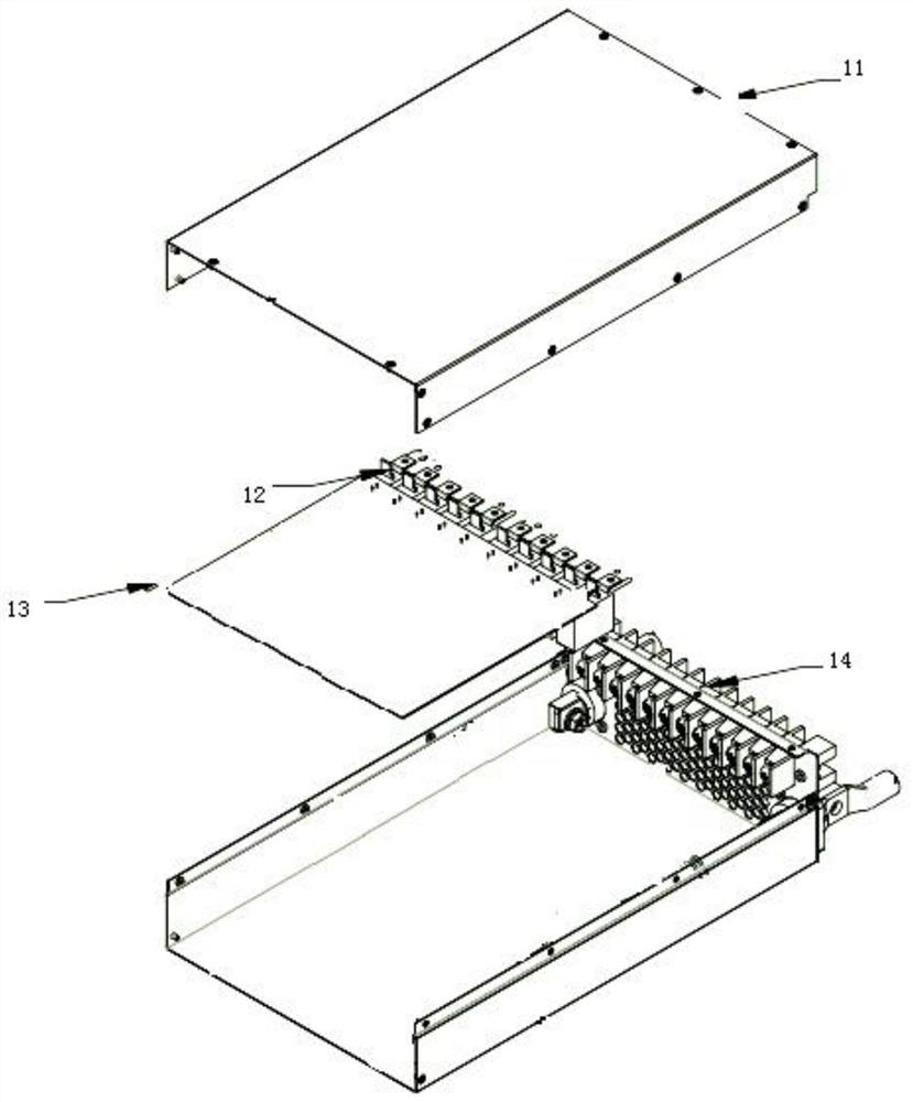
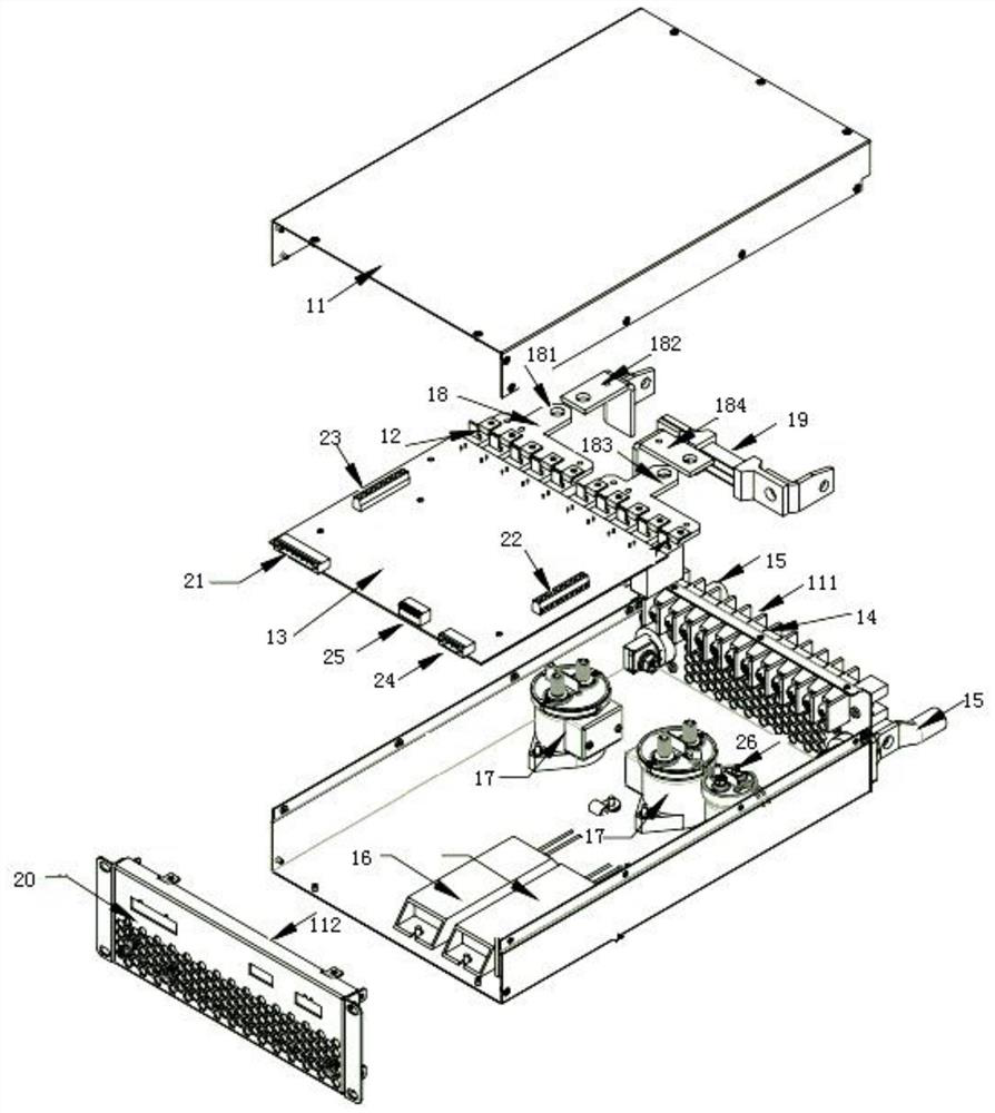
[0020] See figure 1 , figure 1 A structural diagram of a DC charging unit provided by an embodiment of the present invention, the DC charging unit includes:

[0021] Electric box body 11, the inside of electric box body 11 is provided with magnetic latching relay 12, is also provided with the control panel 13 that is used to control magnetic latching relay 12 in electric box body 11, is also provided with on the first side wall 111 of electric box body 11 Th...


PUM


Abstract

The invention discloses a direct-current charging unit which is applied to a matrix type charging system and comprises an electrical box body, a magnetic latching relay is arranged in the electrical box body, and a control panel used for controlling the magnetic latching relay is further arranged in the electrical box body. The first side wall of the electrical box body is also provided with a plurality of wiring terminals for establishing electrical connection between the magnetic latching relay and the target charging module. Obviously, since the magnetic latching relay has a smaller space volume compared with a direct current switching contactor, the space volume occupied when the matrix type charging system is built can be relatively reduced, and the space area occupied by the matrix type charging system is reduced. Correspondingly, the matrix type charging system disclosed by the invention also has the above beneficial effects.

Description

technical field [0001] The invention relates to the technical field of charging, in particular to a DC charging unit and a matrix charging system. Background technique [0002] Electric vehicles have been widely promoted around the world because of their advantages of energy saving and environmental protection. At present, in order to solve the problems of large footprint and low charging power of DC charging piles, in the prior art, DC switching contactors are generally used to build multiple charging modules together, so that these charging modules can form a matrix charging control system. However, due to the bulky volume of the DC switching contactor, the matrix charging system constructed by the DC switching contactor needs to occupy a relatively large space area. For this technical problem, there is no comparatively effective solution now. [0003] It can be seen that how to further reduce the space occupied by the matrix charging system is a technical problem to be...

Claims


Application Information

Patent Timeline
Patent Type & Authority Applications(China)
IPC IPC(8): H02J7/00H02B1/48H02B1/20H02B1/56
CPCH02J7/0013H02J7/0042H02J7/00032H02B1/48H02B1/20H02B1/56
Inventor 卜宪林王立军胡勇庄德才尚文政侯仁泉崔亚鹏单修泽田诚信李林王海生毕瀚中蒋洪轩高冲杨元锋
Owner SHANDONG LUNENG SOFTWARE TECH
Why Eureka
Try Eureka