
Joint hinge

A joint and hinge technology, applied in the field of medical equipment, can solve the problems of flexibility and large load-bearing capacity.

Pending Publication Date: 2021-04-06
SUZHOU HAOBRO MEDICAL DEVICE
View PDF0 Cites 0 Cited by
  • Summary
  • Abstract
  • Description
  • Claims
  • Application Information

AI Technical Summary

Problems solved by technology

[0004] In order to solve the characteristics that the existing damping hinges cannot balance flexibility and large load-bearing capacity, the present invention provides a joint hinge

Method used


Image

  • Joint hinge
  • Joint hinge
  • Joint hinge

Examples


Embodiment

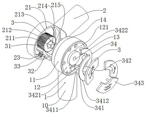
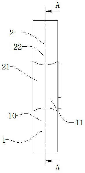
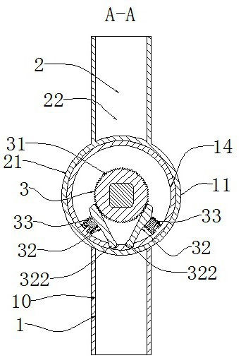
[0021]See attachmentFigure 1-4An articulated hinge comprising: the first joint 1, the second joint 2, the lock mechanism 3;

[0022]The first joint 1, the second joint 2 is hinged to each other, and the locking mechanism 3 is connected to each other with the first joint 1, and the second joint 2;

[0023]The locking mechanism 3 is used to lock the position of the first joint 1 and the second joint 2;

[0024]The first joint 1 includes a first hinge portion 11, a first arm mounting portion 10;

[0025]The first hinge portion 11 is provided in a cylindrical shape, and a fixed support plate 12 is provided on one side of the first hinge portion 11;

[0026]The outer side of the fixed support plate 12 is parallel to the first hinge 11;

[0027]The outer surface of the fixed support plate 12 is provided with an annular groove 121;

[0028]The fixing hole 13 of the second joint 2 is provided in the fixed support plate 12;

[0029]The first arm mounting portion 10 is fixed to the first hinge 11;

[0030]The first arm...


PUM


Abstract

The invention discloses a joint hinge. The joint hinge comprises a first joint, a second joint and a locking mechanism. The first joint and the second joint are hinged to each other, and the locking mechanism is connected with the first joint and the second joint. The locking mechanism is used for locking the positions of the first joint and the second joint. The locking mechanism comprises a ratchet wheel fixedly installed on the second joint and pawls arranged on the first joint. The ratchet wheel and the pawls are arranged in a mutual meshing mode. By means of the design mode that the ratchet wheel and the pawls are matched with each other, rotating locking in two rotating directions can be conducted, an unlocking device can achieve three aims including unlocking in two independent rotating directions and complete unlocking, and at the moment, the joints can be freely adjusted. The structure is simple, the number of parts is extremely small, machining is facilitated, and use is convenient. During angle adjusting, the angle adjusting precision can be limited according to the tooth numbers of the ratchet wheel and the pawls.

Description

Technical field[0001]The present invention belongs to the technical field of medical equipment, and more particularly to a joint hinge.Background technique[0002]The joint hinge is a commonly used component for connecting two arms, and the two arm connectors can be arbitrarily rotated using the joint hinge, and the joint hinge having the lock function can be locked in the formulation position to ensure two support The relative position of the arm is kept fixed, and the coach that locks in the in-place location has a wide range of uses, often used in office equipment, medical equipment, etc.[0003]However, the structure of the conventional joint hinge is more damping, which can be stopped in any position and a wide range of trials. However, this structure cannot be taken into considerable in flexibility and greater load-bearing, and the flexibility of the damping hinge cannot withstand a large weight; the hinges that can withstand large weight are often less likely to rotate the angle....

Claims


Application Information

Patent Timeline
IPC IPC(8): F16C11/04F16C11/10F16D41/12
CPCF16C11/04F16C11/103F16D41/12
Inventor 祖慧鹏王品军
Owner SUZHOU HAOBRO MEDICAL DEVICE
Learn More