
Prefabricated combined road and bridge anti-collision side edge protection structure

A protective structure and combined technology, applied in the direction of roads, bridges, roads, etc., can solve the problems of buffer structure failure, inability to disassemble and replace, and poor structural connection stability, so as to achieve good anti-collision ability and improve connection stability.

Inactive Publication Date: 2021-04-06
陈祖友
View PDF14 Cites 4 Cited by
  • Summary
  • Abstract
  • Description
  • Claims
  • Application Information

AI Technical Summary

Problems solved by technology

[0006] The purpose of the present invention is to provide a prefabricated combined anti-collision side protection structure for road bridges, to solve the problem that the existing protection structures on the market proposed by the above-mentioned background technology will have a buffer structure that will fail after the impact airbag is ruptured, and cannot Restoration, after the accident is resolved, it must be replaced regardless of whether the device is damaged, and the existing protective structure cannot be disassembled and replaced separately after the local collision damage occurs, and the original structure after reassembly problem with poor connection stability

Method used


Image

  • Prefabricated combined road and bridge anti-collision side edge protection structure
  • Prefabricated combined road and bridge anti-collision side edge protection structure
  • Prefabricated combined road and bridge anti-collision side edge protection structure

Examples


Embodiment Construction

[0030] The following will clearly and completely describe the technical solutions in the embodiments of the present invention with reference to the accompanying drawings in the embodiments of the present invention. Obviously, the described embodiments are only some, not all, embodiments of the present invention. Based on the embodiments of the present invention, all other embodiments obtained by persons of ordinary skill in the art without making creative efforts belong to the protection scope of the present invention.

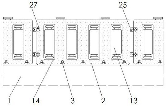
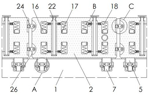
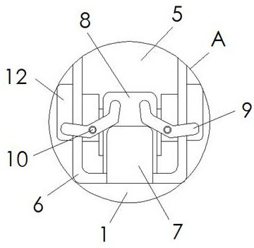
[0031] see Figure 1-9 , the present invention provides a technical solution: a prefabricated combined road bridge anti-collision side protection structure, including an installation base 1, an installation plate 2, reserved bolts 3, support blocks 4, connecting blocks 5, and reserved grooves 6 , fixed block 7, connecting groove 8, card plate 9, connecting shaft 10, torsion spring 11, card groove 12, guide cylinder 13, mounting frame 14, support plate 15, buff...


PUM


Abstract

The invention discloses a prefabricated combined road and bridge anti-collision side edge protection structure which comprises a mounting base surface, a mounting plate, reserved bolts and supporting blocks, the mounting plate is arranged above the mounting base surface, the supporting blocks are arranged on the rear side of the mounting plate, and the reserved bolts penetrate through the front side and the rear side of the mounting plate; the reserved bolts are fixed in the mounting base surface, a connecting block is embedded in the lower portion of the mounting plate, a reserved groove is formed in the outer side of the connecting block, the reserved groove is formed in the upper surface of the mounting base surface, a guide cylinder is arranged on the front side of the mounting plate, and a mounting frame is connected to the outer side of the guide cylinder; and a supporting plate is mounted at the rear end of the mounting frame. The prefabricated combined road and bridge anti-collision side edge protection structure is provided with fixing blocks, clamping plates and mounting shafts, the clamping plates can be pushed to move through the fixing blocks, the clamping plates are connected with the clamping grooves, so that the connecting stability between the connecting blocks and the reserved grooves is improved, and the structure has better anti-collision capacity.

Description

technical field [0001] The invention relates to the technical field of anti-collision of road bridges, in particular to a prefabricated combined anti-collision side protection structure of road bridges. Background technique [0002] The road bridge anti-collision structure is the main protective structure on the side of the bridge. The road bridge is surrounded by the protective structure on the side plate of the bridge to prevent vehicles from directly rushing down the bridge. The public number is CN210238267U, which discloses a kind of anti-collision telescopic structure for road bridges. , the root position of the side of the support column is provided with a symmetrical blade, and the blade is fixedly connected with the support column screw. The column is against the airbag, and the vehicle is protected by cushioning with the elasticity of the airbag. When the vehicle collides at a high speed and high speed, the impact force on the impact panel is relatively large. If th...

Claims


Application Information

Patent Timeline
IPC IPC(8): E01F15/08E01D19/00F16F15/067
CPCE01D19/00E01F15/08F16F15/067
Inventor 陈祖友
Owner 陈祖友
Learn More