
Power tracking excitation control method and system for dual-shaft excitation generators

A generator power and excitation control technology, applied in the control system, controlling the generator through the change of the magnetic field, controlling the generator, etc., can solve the problem of long dynamic process of double exciter, large oscillation amplitude, unfavorable power system stable operation, etc. problems, to achieve the effect of ensuring stability, reducing oscillation amplitude and oscillation time, and thermal load balance

Active Publication Date: 2022-07-05
NORTH CHINA ELECTRIC POWER UNIV (BAODING)
View PDF7 Cites 0 Cited by
  • Summary
  • Abstract
  • Description
  • Claims
  • Application Information

AI Technical Summary

Problems solved by technology

The dynamic process of the double exciter using the traditional dual-channel excitation control strategy takes a long time and the oscillation amplitude is large, which is not conducive to the stable operation of the power system

Method used


Image

  • Power tracking excitation control method and system for dual-shaft excitation generators
  • Power tracking excitation control method and system for dual-shaft excitation generators
  • Power tracking excitation control method and system for dual-shaft excitation generators

Examples


Embodiment 1

[0051] A dual-shaft excitation generator power tracking excitation control method

[0052] Active power tracking control:

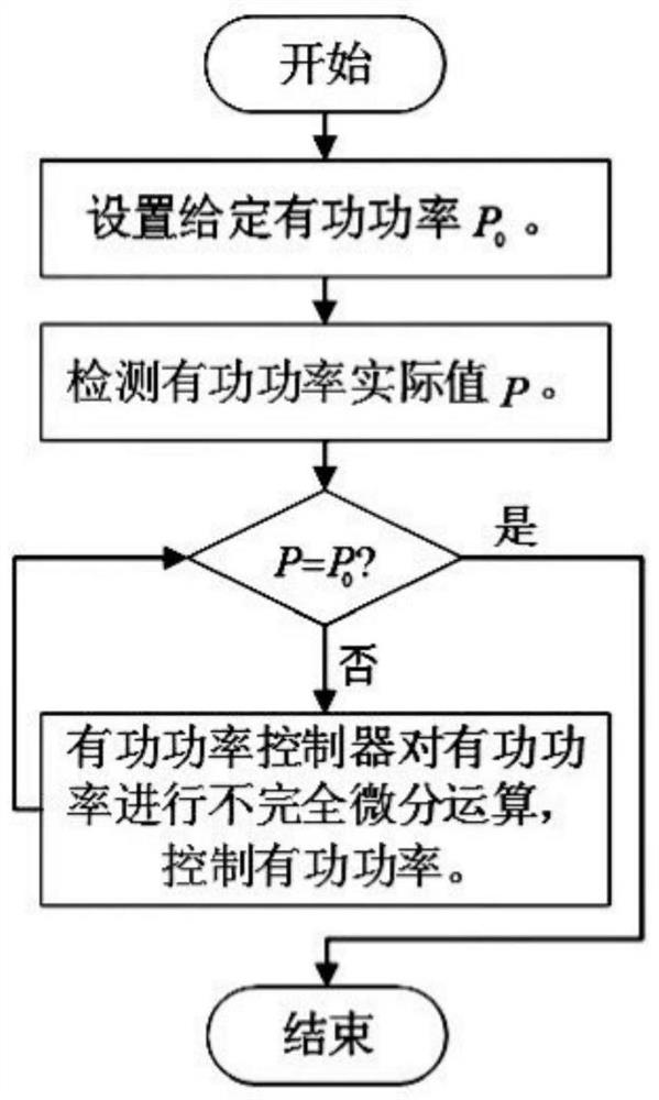
[0053] like figure 1 As shown, the active power of the motor is tracked and controlled by the q-axis power tracking excitation control system, so that the actual value P of the active power is equal to the given value P of the active power 0 .

[0054] Through the q-axis power tracking excitation control system, the active power of the motor is incompletely differentiated, and the active power of the motor is tracked and controlled, and the adjustment value W of the q-axis excitation voltage is obtained by the following formula P ,

[0055]

[0056] In the formula, ΔP=P 0 -P,P 0 is the given active power value, P is the actual value of active power; K P , T dP , K dP are the proportional coefficient, differential time constant and incomplete differential factor of the active power controller, respectively; r f / x af In order to reduce the exc...

Embodiment 2

[0073] Power Tracking Excitation Control System for Dual Shaft Excited Generator

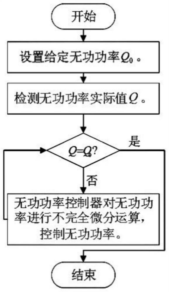
[0074]It includes a q-axis power tracking excitation control system and a d-axis power tracking excitation control system; the q-axis power tracking excitation control system includes an active power controller and an excitation current controller, and the active power controller can track the active power of the motor. The excitation current controller can track and control the motor excitation current; the d-axis power tracking excitation control system includes a reactive power controller, and the reactive power controller can track and control the motor reactive power.

[0075] The q-axis power tracking excitation control system is arranged on the q-axis excitation winding of the motor, and the d-axis power tracking excitation control system is arranged on the d-axis excitation winding.

[0076] Also includes a detection device for detecting the actual values ​​P, Q, i of the active power, r...


PUM


Abstract

The invention relates to a power tracking excitation control method and system for a dual-axis excitation generator. The q-axis power tracking excitation control system is used to track and control the active power of the motor, so that the actual value P of the active power is equal to the given active power value P. 0 ;The reactive power of the motor is tracked and controlled by the d-axis power tracking excitation control system, so that the actual value of reactive power Q is equal to the given value of reactive power Q 0 ; The motor excitation current is tracked and controlled by the q-axis power tracking excitation control system, so that the q-axis excitation current i fq Equal to the d-axis excitation current i fd . The invention can effectively control the power, shorten the dynamic process and reduce the oscillation amplitude.

Description

technical field [0001] The invention relates to a power tracking excitation control method and system of a dual-shaft excitation generator. Background technique [0002] With the increase of single-unit capacity and the development of UHV long-distance power transmission, the angle between the excitation electromotive force of the synchronous generator and the system voltage is getting closer and closer to the limit value, which reduces the stability of the generator and power system. [0003] The traditional synchronous generator has only one set of excitation windings, which is placed on the d-axis of the rotor. This feature determines that its power regulation and operation stability are related to the angle between the generator's longitudinal axis of the magnetomotive force and the grid voltage, that is, with The generator power angle is related, limiting the range of operating stability. The dual-axis excitation generator (dual-exciter) is provided with excitation win...

Claims


Application Information

Patent Timeline
Patent Type & Authority Patents(China)
IPC IPC(8): H02P9/00H02P9/14
CPCH02P9/008H02P9/14Y02E40/30
Inventor 许国瑞王珍珍李伟力罗应立
Owner NORTH CHINA ELECTRIC POWER UNIV (BAODING)
Learn More