


Quick Research
Generate reliable direction feasibility study reports for your R&D in just a few steps.

Technical Q&A
Discover and master advanced knowledge NOW. Basics, ideas, possibilities, all at once.

Find Solutions
As an expert in R&D theories, this can generate solutions to your technical problems instantly.

Evaluate Feasibility
Analyze your overall solution with one click, know your potential R&D risks in advance.

Monitor Landscape
Get weekly tech updates, stay abreast of the latest tech innovations and key insights.
A portable car-loading device
A portable and automotive technology, applied in motor vehicles, trolleys, trolley accessories, etc., can solve problems such as inconvenient use, complicated operation, and single function
- Summary
- Abstract
- Description
- Claims
- Application Information
AI Technical Summary
Problems solved by technology
Method used
Image

Examples
Embodiment 1
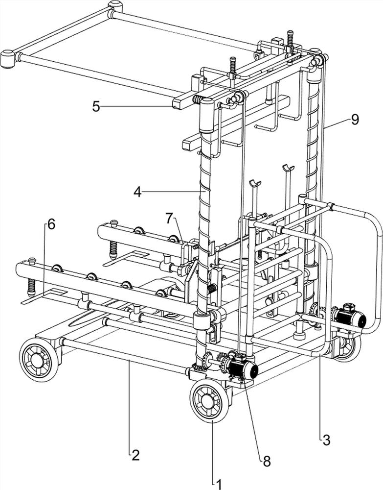
[0080] A portable car support device, such as figure 1 As shown, it includes an electric wheel 1, a mounting plate 2, a hand push rod 3, a lifting mechanism 4 and a pushing mechanism 5. The bottom of the mounting plate 2 is rotatably provided with an electric wheel 1 on the front and rear sides, and the front side of the top of the mounting plate 2 is provided with an electric wheel 1. There is a hand push rod 3 , a lift mechanism 4 is arranged on the front part of the top side of the mounting plate 2 , and a push mechanism 5 is arranged on the lift mechanism 4 .
[0081] When people need to transfer the faulty car to the truck, first people start the electric wheel 1, so that the electric wheel 1 rotates on the ground, and then the mounting plate 2 moves, so as to make the push rod 3 and the lifting mechanism 4 move, and the lifting mechanism 4 Moves to drive the push mechanism 5, so that the device moves, and at the same time people grab the hand push rod 3 to control the di...
Embodiment 2
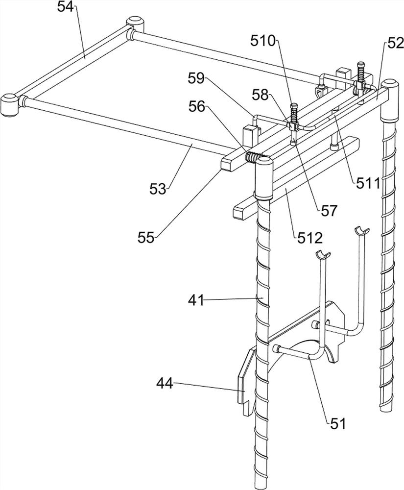
[0083] On the basis of Example 1, as figure 2 and image 3 As shown, the lifting mechanism 4 includes a screw 41, a nut 42, a moving plate 43, a baffle 44 and a wheel 45. The left and right sides of the front part of the top side of the mounting plate 2 are rotatably provided with screws 41. A nut 42 is provided in the uniform thread type, a moving plate 43 is connected between the nuts 42 on the left and right sides, a baffle plate 44 is connected between the left and right sides of the front part of the moving plate 43, and the left and right sides of the top of the moving plate 43 are rotatable. Four wheels 45.
[0084] When the mounting plate 2 moves, the mounting plate 2 drives the screw 41 to move, and then the nut 42 moves, and the movement of the nut 42 makes the moving plate 43 move, thereby making the baffle 44 and the wheel 45 move, and then people move the mounting plate 2 to the lower part of the car , At the same time, the car is matched with the moving plate ...
Embodiment 3
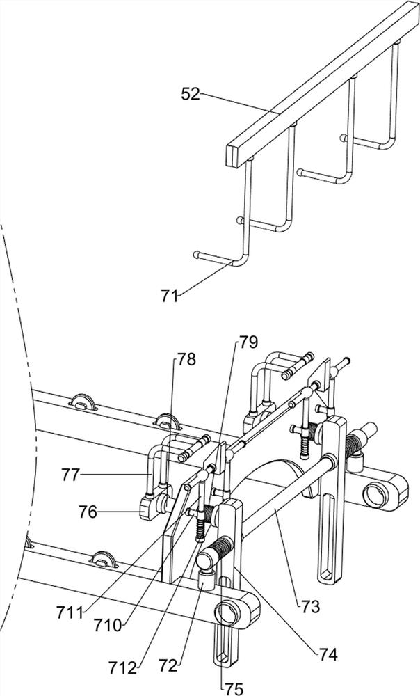
[0088] On the basis of Example 2, as figure 1 , Figure 4 , Figure 5 , Image 6 and Figure 7 As shown, a blocking mechanism 6 is also included. The blocking mechanism 6 includes a second sliding sleeve 61, a third sliding rod 62, an inclined plane block 63, a fourth sliding rod 64, a ball 65 and a third spring 66. The bottom of the moving plate 43 is left and right. There are two second sliding sleeves 61 on both sides, a third sliding rod 62 is slidably connected between the inner sides of the second sliding sleeves 61 on the front and rear sides, and the rear sides of the third sliding rods 62 on the left and right sides are provided with inclined surfaces. Block 63, the left and right sides of the rear of the moving plate 43 are slidably provided with fourth sliding bars 64, the bottoms of the fourth sliding bars 64 on the left and right sides are rotatably provided with balls 65, and the fourth sliding bars 64 on the left and right sides are rotatably provided with ba...
PUM
 Abstract
Description
Claims
Application Information
 - R&D Engineer
- R&D Manager
- IP Professional
- Industry Leading Data Capabilities
- Powerful AI technology
- Patent DNA Extraction
Browse by: Latest US Patents, China's latest patents, Technical Efficacy Thesaurus, Application Domain, Technology Topic, Popular Technical Reports.
© 2024 PatSnap. All rights reserved.Legal|Privacy policy|Modern Slavery Act Transparency Statement|Sitemap|About US| Contact US: help@patsnap.com