Agricultural portable pesticide spraying device
A kind of pesticide spraying and convenient technology, which is applied in spraying devices, devices for catching or killing insects, animal husbandry, etc., can solve the problem that pesticides are not easy to be sprayed evenly, so as to reduce the time of spraying pesticides, optimize functions, and evenly spray pesticides Effect
- Summary
- Abstract
- Description
- Claims
- Application Information
AI Technical Summary
Problems solved by technology
Method used
Image
Examples
Embodiment 1
[0022]A agricultural convenience pesticide spraying device, such asfigure 1 ,figure 2 withimage 3 As shown, including the wheel 1, the mounting plate 2, the strut 3, the discharge frame 4, the spray mechanism 5, and the swing mechanism 6, and the mounting plate 2 is uniformly rotated on both sides, and the mounting plate 2 is provided on the rear side. The pillar 3, the strut 3 is provided with a discharge frame 4, and a spraying mechanism 5 is provided on the mounting plate 2, and a swing mechanism 6 is provided on the mounting plate 2.
[0023]First, the pesticide is poured into the discharge frame 4, and then the spray mechanism 5 is turned on. The operation of the spraying mechanism 5 will drive the operation of the swing mechanism 6, thereby achieving the purpose of pesticide spraying, after the spray is completed, close the spray mechanism 5 The spray mechanism 5 stops operation will cause the swing mechanism 6 to stop operation, if you need to spray the pesticide again, repeat t...
Embodiment 2
[0025]On the basis of Example 1, such asfigure 1 ,figure 2 ,image 3 As shown, the spray mechanism 5 includes a mounting frame 51, a biaxial motor 52, a bracket 53, a rotating shaft 54, a tab 55, a storage frame 56, a telescopic hose 561, a shower 57, a push rod 58, a slider 59, The slider 510 and the compression spring 511, the mounting plate 2 is uniformly provided with four brackets 53, and the two brackets 53 on the left side and the two brackets 53 on the right side are provided with a storage frame 56, the discharge frame 4 The material frame 56 is connected to the storage frame 56, and the sliding sleeve 59 is provided in front and rear, and the inner sliding type sliding gear is provided with the sliding rod 510 on the front and rear sides, and the slider 510 has a compression spring 511, the outer side of the compression spring 511. Both are connected to the slide 59, and the inner side of the slider 510 on the left and right sides is provided with a push rod 58, and the out...
Embodiment 3
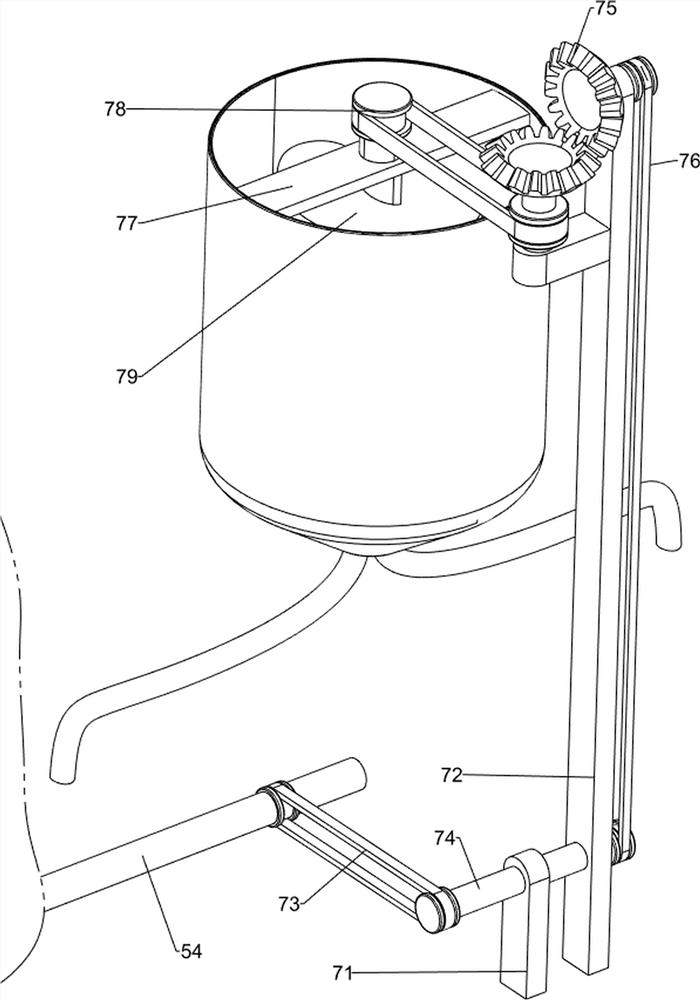
[0030]On the basis of Example 2, such asfigure 1 withFigure 4As shown, a stirring mechanism 7 is further included, and a stirring mechanism 7 is provided on the front side on the front side, the stirring mechanism 7 includes a support frame 71, a support post 72, a conveyor belt 73, a third shaft 74, a cone 75, first The transmission assembly 76, the support plate 77, the second transmission assembly 78, and the stirring rod 79, and the mounting plate 2 is provided with a support post 72, and the upper rotation of the support post 72 is provided with a cone gear set 75, and the upper portion of the discharge frame 4 is provided. The support plate 77, the support plate 77 is rotatable, and the stirring lever 79 is located inside the discharge frame 4, and the mixing rod 79 and the taper gear set 75 are wound around the second transmission assembly 78, the mounting plate 2 upper front side A support frame 71 is provided, and the support frame 71 is rotating is provided with a third ro...
PUM
 Abstract
Description
Claims
Application Information
 - R&D
- Intellectual Property
- Life Sciences
- Materials
- Tech Scout
- Unparalleled Data Quality
- Higher Quality Content
- 60% Fewer Hallucinations
Browse by: Latest US Patents, China's latest patents, Technical Efficacy Thesaurus, Application Domain, Technology Topic, Popular Technical Reports.
© 2025 PatSnap. All rights reserved.Legal|Privacy policy|Modern Slavery Act Transparency Statement|Sitemap|About US| Contact US: help@patsnap.com


