Soft package battery test probe

A soft package battery and test probe technology, which is applied to the parts of electrical measuring instruments, measuring electricity, measuring devices, etc., can solve the problems that the probe is easy to damage the surface of the battery tab, the contact resistance is large, and it is inconvenient to be compatible. It achieves the effects of convenient type change, high contact resistance and wide application range

Inactive Publication Date: 2021-03-30
ZHEJIANG HANGKE TECH
View PDF0 Cites 0 Cited by
  • Summary
  • Abstract
  • Description
  • Claims
  • Application Information

AI Technical Summary

Problems solved by technology

However, there are some problems in the existing probe technology. First, there is the problem of matching the size of the battery tab with the probe, that is, it is inconvenient to be compatible; second, the contact resistance between the probe and the battery tab is large; The needle is easy to damage the surface of the battery tab

Method used


Image

  • Soft package battery test probe
  • Soft package battery test probe
  • Soft package battery test probe

Examples


Embodiment 1

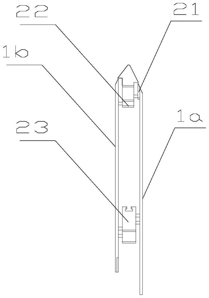
[0023] Embodiment 1 A test probe for a pouch battery according to the present invention includes a lug contact plate 1 for realizing circuit conduction between the battery and the test mechanism, a fixing unit 2 for fixing the probe, and a Magnet unit 3 clamping the lug, wherein:

[0024] The tab contact plate 1 is a conductive device, including a first guide plate body 1a and a second guide plate body 1b parallel to the first guide plate body, and the head and tail ends of the inner end surfaces of the first and second guide plate bodies Both have installation areas, and keep the installation areas of the two guide plates facing each other to form a gap for installing the fixing unit; the outer end surface of the first guide plate body is provided with a tab contact area for contacting and connecting with the tabs of the pouch battery 11. The tab contact area 11 is provided with a signal connection terminal, which is used to electrically connect with an external test device t...

Embodiment 2

[0034] Embodiment 2 The difference between this embodiment and Embodiment 1 is: from figure 1 It can be seen that the lug contact plate is the bottom layer, and the two ends of the lug contact plate are respectively fixed with the head mount of the printed board and the bottom slider of the printed board by screws; the inner surface of the printed board is installed with the magnet unit 3 .

[0035] From figure 2 and image 3 It can be seen that the mounting part on the head of the printed board has screw holes for fixing the tab contact plate; the slider at the bottom of the printed board has screw holes for fixing the tab contact plate.


PUM


Abstract

The invention discloses a soft package battery test probe, which comprises a tab contact plate, a fixing unit and a magnet unit, wherein the tab contact plate is a conductive device and comprises a first guide plate body and a second guide plate body, and mounting areas are arranged at the head and tail ends of the inner end faces of the first guide plate body and the second guide plate body; thetab contact area is arranged on the outer end surface of the first guide plate body and is provided with a signal connecting end; the fixing unit is an insulating device, is clamped between the firstguide plate body and the second guide plate body and comprises a printed board guide block, a printed board head mounting piece and a printed board bottom sliding block, the printed board guide blockis mounted in the mounting area of the head of the inner end surface of the first guide plate body, the printed board head mounting piece and the printed board bottom sliding block are fixedly connected with the mounting areas at the head and tail parts of the first guide plate and the second guide plate respectively; the end face, which faces the head mounting piece, of the printed board bottom sliding block is provided with a sliding groove; and the magnet unit is mounted on the inner surface of the second guide plate body. The beneficial effects of the invention are that the soft package battery test probe is convenient in matching replacement operation, is high in crimping reliability, and is higher in compatibility.

Description

technical field [0001] The invention relates to a test probe for a soft pack battery, which belongs to the field of battery testing. Background technique [0002] In the traditional formation and capacity test of pouch batteries, the connection between the battery and the test equipment mainly relies on the form of alligator clips. Using this method, there are troublesome wiring, many wiring, and the risk of easy misconnection. Therefore, the electrical connection between the external transmission wire and the battery tab is an important basic component in the battery formation and capacity distribution equipment, and it is an extremely important component. For this reason, the use of probe connection is a good connection method, which can realize reliable connection between the battery tab and the charging and discharging equipment, which is easy to operate and improves work efficiency. However, there are some problems in the existing probe technology. First, there is the ...

Claims


Application Information

Patent Timeline
Patent Type & Authority Applications(China)
IPC IPC(8): G01R1/067G01R31/36
CPCG01R1/06711G01R31/3644
Inventor 曹骥曹政郭凯华刘伟章炜军张齐
Owner ZHEJIANG HANGKE TECH
Why Eureka
Try Eureka