Non-contact control type switch

A controlled, non-contact technology, applied to electrical switches, circuit layouts on support structures, electrical components, etc., to solve the problems of infrared pair tube module identification, large detection angle of pyroelectric sensor modules, and inability to structural design.

Pending Publication Date: 2021-03-26
张浩林
View PDF0 Cites 0 Cited by
  • Summary
  • Abstract
  • Description
  • Claims
  • Application Information

AI Technical Summary

Problems solved by technology

[0002] The technology commonly used in non-contact switches is to use the infrared tube module, distance measuring module, pyroelectric sensor module, etc., where the infrared tube module and the distance measuring module cannot identify the operation of the human body. When a foreign object touches the detection port It is easy to cause non-subjective misoperation, and the detection angle of the pyroelectric sensor module is too large, so it cannot be used directly by the user without structural design. The non-contact switch can effectively avoid cross-infection and prevent the spread of diseases, and is widely used in elevators. Switches, light switches and other fields

Method used


Image

  • Non-contact control type switch
  • Non-contact control type switch

Examples


Embodiment

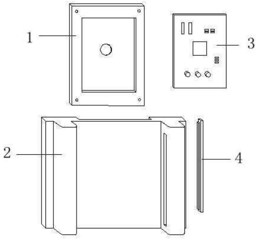
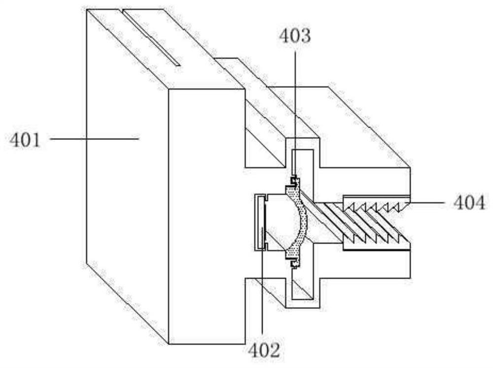
[0013] Taking a non-contact control switch used on an LED lamp as an example, it is characterized in that it includes a motherboard bottom cover 1, a panel 2, a main control board 3, and a pyroelectric sensor module 4; the inside of the motherboard bottom cover 1 There is a cavity for installing the main control board 3, and there are cable perforations on the bottom surface for connecting cables, and the back of the panel 2 is connected by screws; there is a blocking column on the left side of the panel 2, which is used to block light, and a sensor column on the right side , there is a cavity inside for installing the pyroelectric sensor module 4, and the columns on both sides are parallel to the plane of the panel 2; The cavity is used to control the switch on and off; the pyroelectric sensor module 4 is installed in the cavity of the sensor column on the right side of the panel 2 through structural components, and is connected to the main control board 3 through a cable.

...


PUM


Abstract

The invention discloses a non-contact control type switch, and particularly relates to the design of a non-contact switch, in particular to the aspect of structural design improvement of the non-contact control switch by utilizing a pyroelectric sensor. The non-contact control type switch comprises a mainboard bottom cover, a panel, a main control board and a pyroelectric sensor module, A cavity is inside the mainboard bottom cover and is used for installing the main control board, the bottom surface of the mainboard bottom cover is provided with a cable through hole for a cable to pass through and is connected with the back surface of the panel through a screw; the left side of the panel is provided with a blocking column used for blocking light, the right side is provided with a sensor stand column, a cavity used for installing the pyroelectric sensor module is reserved inside, and two side columns are parallel in a panel plane. The main control board is externally connected with a power supply, is fixed in a cavity formed by the back of the panel and the mainboard bottom cover through screws and is used for controlling on-off of the switch; the pyroelectric sensor module is installed in a cavity of the sensor stand column on the right side of the panel through a structural part and connected with the main control panel through a flat cable. The advantage of the invention isthat the non-contact control of the switch is realized.

Description

technical field [0001] The invention discloses a non-contact control switch, in particular relates to the design of the non-contact switch, especially the structural design improvement of the non-contact control switch by using a pyroelectric sensor. Background technique [0002] The technology commonly used in non-contact switches is to use the infrared tube module, distance measuring module, pyroelectric sensor module, etc., where the infrared tube module and the distance measuring module cannot identify the operation of the human body. When a foreign object touches the detection port It is easy to cause non-subjective misoperation, and the detection angle of the pyroelectric sensor module is too large, so it cannot be used directly by the user without structural design. The non-contact switch can effectively avoid cross-infection and prevent the spread of diseases, and is widely used in elevators. Switches, lamp switches and other fields. Contents of the invention [0...

Claims


Application Information

Patent Timeline
IPC IPC(8): H01H9/02H05K7/02H05K7/12G01J5/34
CPCG01J5/34H01H9/0271H05K7/02H05K7/12
Inventor 不公告发明人
Owner 张浩林
Why Eureka
Try Eureka