Eureka AIR delivers breakthrough ideas for toughest innovation challenges, trusted by R&D personnel around the world.

Double-laser scanner calibration method, device and equipment

A calibration method and a technology of a calibration device, which are applied in the field of scanner calibration, can solve problems such as long time spent and complicated operation steps, and achieve the effects of reducing result errors, simple operation steps, and reducing impact

Active Publication Date: 2021-03-26
BLUESWORD INTELLIGENT TECH CO LTD
View PDF6 Cites 2 Cited by
  • Summary
  • Abstract
  • Description
  • Claims
  • Application Information

AI Technical Summary

Problems solved by technology

[0004] However, the current method has great disadvantages, for example: only when the center of the car body is the center of motion, the calculated result is more calibrated; If there is a problem in one aspect, the error of the result will be relatively large, but in actual operation, errors in these two aspects are unavoidable; the operation steps are complicated and it takes a long time

Method used


Image

  • Double-laser scanner calibration method, device and equipment
  • Double-laser scanner calibration method, device and equipment
  • Double-laser scanner calibration method, device and equipment

Examples


Embodiment Construction

[0041] Below in conjunction with accompanying drawing and embodiment the present invention will be further described:

[0042] In order to clearly illustrate the technical features of this solution, the present invention will be described in detail below through specific implementation modes and in conjunction with the accompanying drawings. The following disclosure provides many different embodiments or examples for implementing different structures of the present invention. To simplify the disclosure of the present invention, components and arrangements of specific examples are described below. Furthermore, the present invention may repeat reference numerals and / or letters in different instances. This repetition is for the purpose of simplicity and clarity and does not in itself indicate a relationship between the various embodiments and / or arrangements discussed. It should be noted that components illustrated in the figures are not necessarily drawn to scale. Description...


PUM


Abstract

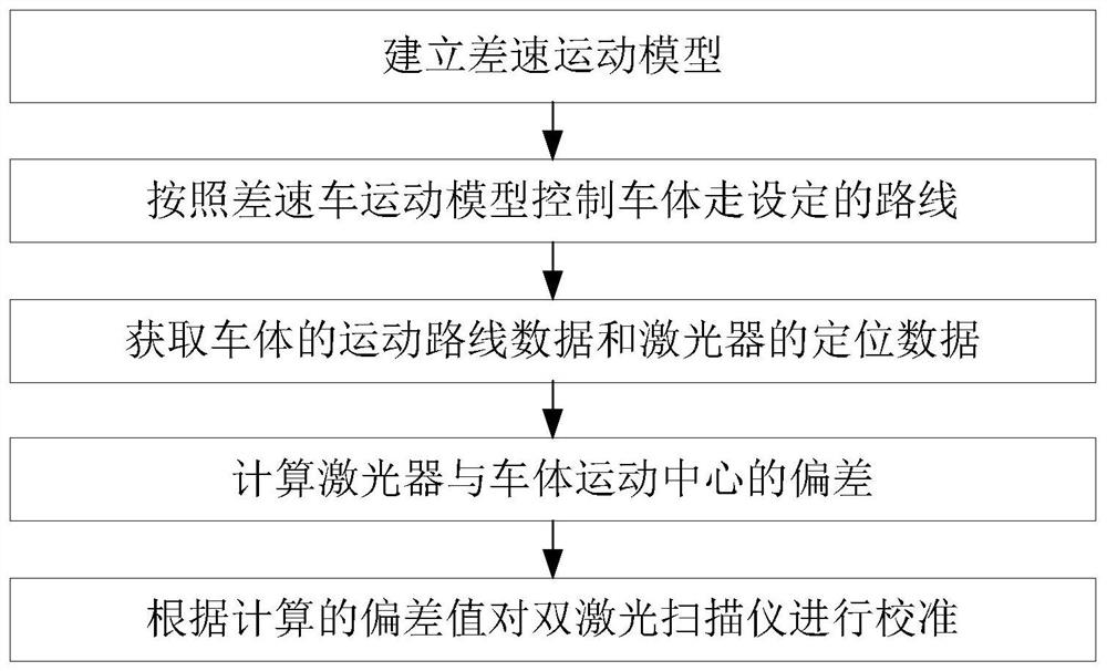
The invention discloses a double-laser scanner calibration method, device and equipment. The method comprises the following steps: establishing a differential motion model; controlling the vehicle body to walk a set route according to the differential vehicle motion model; acquiring motion route data of a vehicle body and positioning data of a laser; calculating the deviation between the laser andthe vehicle body motion center; and calibrating the double-laser scanner according to the calculated deviation value. According to the invention, result errors caused by manual misoperation are reduced; and the influence of the vehicle body machining error on the calibration result is reduced.

Description

technical field [0001] The invention relates to a dual laser scanner calibration method, device and equipment, belonging to the technical field of scanner calibration. Background technique [0002] AGV control needs to be controlled according to the position of the center of motion of the AGV, which requires the positioning part to transfer the positioning point of the laser to the positioning point of the center of the car body. This transfer process requires the position deviation of the laser relative to the center of the car body. For AGVs with dual lasers or multiple lasers, it is necessary to ensure that the positioning results of each laser can be transferred to the center of the car body, and the coordinates of all lasers after transfer are basically the same. [0003] At present, the method of determining the position deviation of the laser relative to the center of the car body is generally to attach four long boards to the surroundings of the car to surround the l...

Claims


Application Information

Patent Timeline
Patent Type & Authority Applications(China)
IPC IPC(8): G01B11/00G01S7/497G05D1/02
CPCG01B11/00G01S7/497G05D1/0231
Inventor 万慧铭徐光运沈长鹏张小艺刘鹏张贻弓
Owner BLUESWORD INTELLIGENT TECH CO LTD
Why Eureka
Eureka Blog
Learn More