
Intelligent building spraying machine

A technology of intelligent building and spraying machine, applied in the direction of building, building structure, etc., can solve the problem of increasing the workload of workers, and achieve the effect of increasing the workload

Active Publication Date: 2021-03-26
CHINA CONSTR FIFTH ENG DIV CORP LTD
View PDF5 Cites 0 Cited by
  • Summary
  • Abstract
  • Description
  • Claims
  • Application Information

AI Technical Summary

Problems solved by technology

[0003] The construction field usually needs to spray cement on the wall, and the spraying machine is usually used in the spraying process. The traditional spraying machine requires the worker to hold the pipe in his hand when spraying, and then use the spraying machine to feed the material from the outlet of the pipe. The cement is sprayed on the wall, and the worker needs to hold the spray pipe to the wall all the time and walk back and forth to make the cement spray evenly. Holding the spray pipe for a long time will cause arm pain and greatly increase the worker's workload. workload

Method used


Image

  • Intelligent building spraying machine
  • Intelligent building spraying machine
  • Intelligent building spraying machine

Examples


Embodiment 1

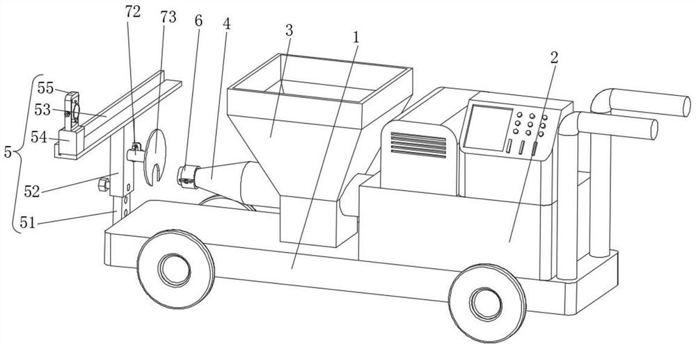
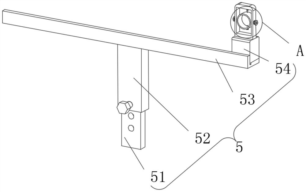
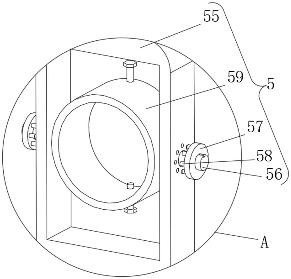
[0030] Example 1, such as Figure 1-8 As shown, the present invention provides an intelligent building spraying machine, including a base plate 1 and an adjustment structure 5, the top of the base plate 1 is fixedly connected with a connection cabinet 2, and the end of the connection cabinet 2 away from the base plate 1 is fixedly connected with a controller and a motor box. The top of the bottom plate 1 is fixedly connected with a material storage frame 3, and a connecting pipe 4 is inserted inside the material storage frame 3. The end of the connecting pipe 4 close to the controller communicates with the connection cabinet 2, and the end of the bottom plate 1 away from the connection cabinet 2 is provided with an adjustment Structure 5.

[0031] Let's talk about the specific settings and effects of its adjusting structure 5, fixing structure 6 and auxiliary structure 7 in detail below.

[0032] Such as figure 1 and Figure 4As shown, the adjustment structure 5 includes a ...

Embodiment 2

[0036] Embodiment 2, on the basis of embodiment 1, as figure 1 and image 3 As shown, the sliding frame 52 is provided with an auxiliary structure 7 near one end of the connecting pipe 4, the auxiliary structure 7 includes a fixed column 71, the surface of the fixed column 71 is fixedly connected with the sliding frame 52, and the surface of the fixed column 71 is slidably connected with a sleeve 72, The end of the sleeve 72 away from the sliding frame 52 is fixedly connected to the limit plate 73, and the end of the sliding frame 52 close to the fixed column 71 is fixedly connected to a rectangular plate 74. A sliding rod 75 is inserted inside the rectangular plate 74, and the surface of the sliding rod 75 is fixed. A long plate 76 is connected, and the end of the slide rod 75 away from the fixed column 71 is fixedly connected with a sphere 77. First, the middle part of the nozzle is wound on the sleeve 72, and then the two ends of the nozzle are connected to the connecting p...


PUM


Abstract

The invention provides an intelligent building spraying machine, and relates to the technical field of spraying machines. The intelligent building spraying machine comprises a bottom plate and an adjusting structure; the top end of the bottom plate is fixedly connected with a connecting cabinet; the end, away from the bottom plate, of the connecting cabinet is fixedly connected with a controller and a motor box; the top end of the bottom plate is fixedly connected with a storage frame; a connecting pipe is inserted into the storage frame; the end, close to the controller, of the connecting pipe is communicated with the connecting cabinet; an adjusting structure is arranged at the end, away from the connecting cabinet, of the bottom plate; the adjusting structure comprises a connecting rod;the surface of the connecting rod is fixedly connected with the bottom plate; the top end of the connecting rod is sleeved with a sliding frame; the inner wall of the sliding frame is slidably connected with the connecting rod; a fixing plate is fixedly connected with the end, away from the connecting rod, of the sliding frame; and a sliding block is slidably connected with the surface of the fixing plate. Through the arrangement of the adjusting structure, the intelligent building spraying machine solves the problem that workers need to hold a spray pipe with hands all the time in the spraying process, and the labor amount is greatly increased.

Description

technical field [0001] The invention relates to the technical field of spraying machines, in particular to an intelligent building spraying machine. Background technique [0002] Spraying machine is a special coating equipment using spraying technology. The principle is to control the air flow to instantly push the air distribution reversing device to change direction, so that the piston of the air motor makes a stable and continuous reciprocating motion, pressurizes the inhaled paint, and passes through the high-pressure soft The tube transports the paint to the spray gun of the sprayer, and the spray gun atomizes the paint instantly and releases it to the surface of the object to be coated. The spraying machine is mainly composed of a feeding device, a spray gun, and an atomization source. Suitable for leather handbags, gift packaging, furniture, footwear, automobile manufacturing and other industries. [0003] The construction field usually needs to spray cement on the ...

Claims


Application Information

Patent Timeline
Patent Type & Authority Applications(China)
IPC IPC(8): E04F21/08
CPCE04F21/08
Inventor 徐玉祥
Owner CHINA CONSTR FIFTH ENG DIV CORP LTD
Learn More