Automatic cover clamping equipment for steel glue barrel
An automatic, glue bucket technology, applied in the direction of flanged bottle caps, etc., can solve the problems of easy arm soreness, general cap clamping effect, time-consuming and labor-intensive problems, etc.
- Summary
- Abstract
- Description
- Claims
- Application Information
AI Technical Summary
Problems solved by technology
Method used
Image
Examples
Embodiment 1
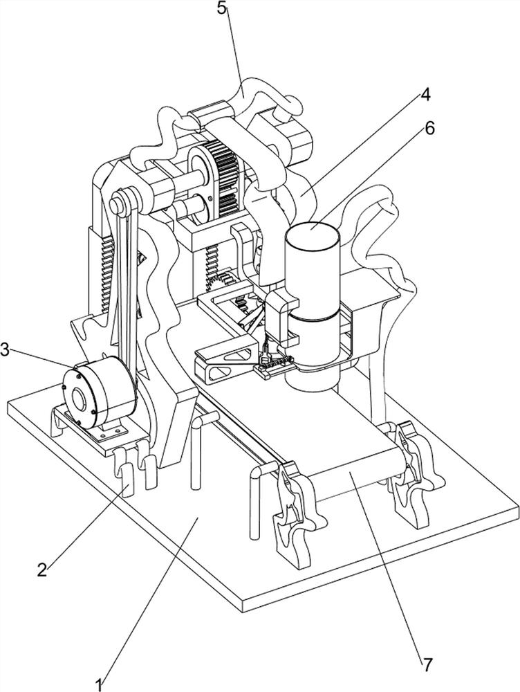
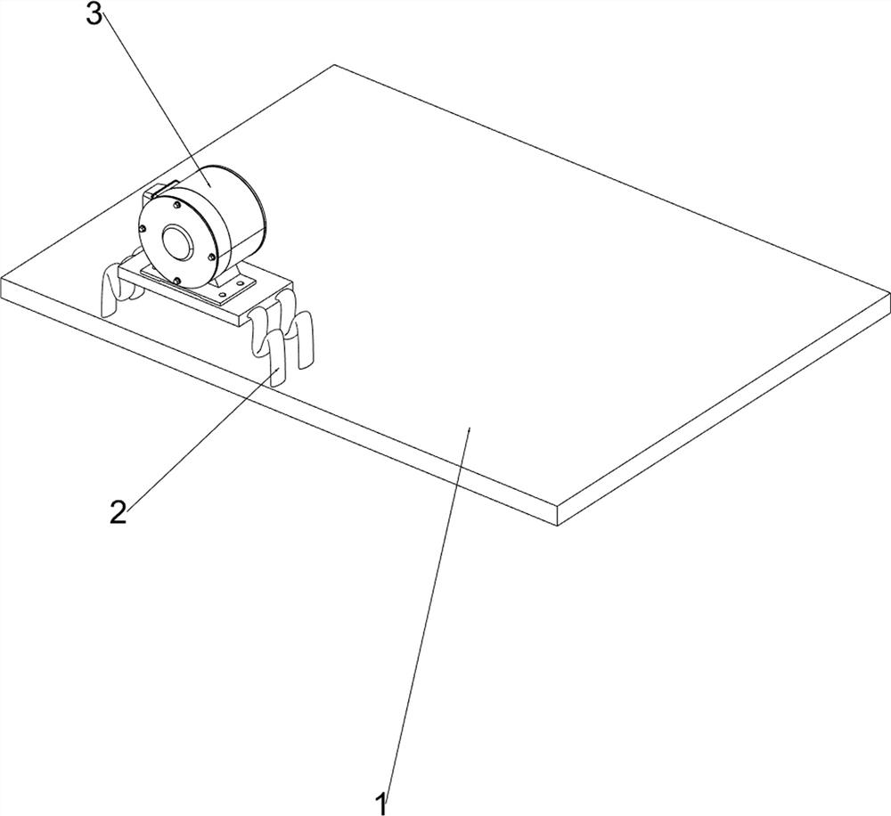
[0023] A kind of automatic cover clamping equipment for steel and plastic barrels, such as figure 1 and figure 2 As shown, it includes a base plate 1, a table 2, a motor 3, a compression mechanism 4 and a clamping mechanism 5, a table 2 is arranged at the left rear portion of the base plate 1, a motor 3 is installed on the top of the table 2, and a motor 3 is installed on the upper rear portion of the base plate 1. Compression mechanism 4, compression mechanism 4 is connected with the output shaft of motor 3, and the upper part of compression mechanism 4 is provided with clamping mechanism 5.
[0024] When people need to clamp and reinforce the steel plastic drum, this clamping equipment can be used. First, people put the steel rubber drum with the cover on the bottom plate 1 directly below the clamping mechanism 5, and then people start the motor 3, The rotation of the output shaft of the motor 3 drives the operation of the compression mechanism 4, thereby driving the mater...
Embodiment 2
[0026] On the basis of Example 1, such as image 3 and Figure 4 As shown, the compression mechanism 4 includes a first support frame 41, a first rotating shaft 42, a second rotating shaft 43, a belt set 44, a first telescopic rod 45, a first gear set 46, a fixed paddle 47, a first fixed Rod 48, the first fixed frame 49, the second fixed rod 410 and the first spring 411, the bottom plate 1 is provided with the first supporting frame 41 on the left and right sides of the upper rear part, and the output shaft of the motor 3 is connected with the first rotating shaft 42, A second rotating shaft 43 is rotationally connected between the tops of the two first support frames 41, and a belt set 44 is connected between the first rotating shaft 42 and the left side of the second rotating shaft 43. The first telescopic rod 45 is provided, and the first fixed mount 49 is arranged between the two first telescopic rods 45 tops. Between the left and right sides of the fixed rod 48, a fixed...
Embodiment 3
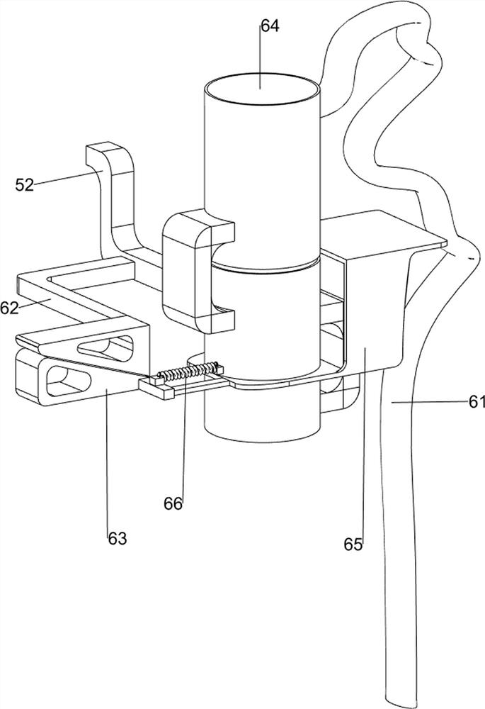
[0031] On the basis of Example 2, such as Figure 5 and Figure 6 As shown, it also includes a feeding mechanism 6, which is provided with a feeding mechanism 6 in the middle of the upper right side of the bottom plate 1. The feeding mechanism 6 includes a second support frame 61, the seventh fixed rod 62, the first movable rod 63, and Fixed plate 64, blanking baffle plate 65 and the third spring 66, bottom plate 1 is provided with the second support frame 61 in the middle of the right side, the third fixed rod 52 left wall is provided with the seventh fixed rod 62, the second support frame 61 top A blanking fixed plate 64 is provided, and the lower part of the blanking fixed plate 64 is slidingly provided with a blanking baffle 65, and the left end of the blanking baffle 65 is provided with a first movable rod 63, and the first movable rod 63 is located below the seventh fixed rod 62 , the first movable rod 63 is in contact with the seventh fixed rod 62 , and a third spring ...
PUM
 Abstract
Description
Claims
Application Information
 - R&D
- Intellectual Property
- Life Sciences
- Materials
- Tech Scout
- Unparalleled Data Quality
- Higher Quality Content
- 60% Fewer Hallucinations
Browse by: Latest US Patents, China's latest patents, Technical Efficacy Thesaurus, Application Domain, Technology Topic, Popular Technical Reports.
© 2025 PatSnap. All rights reserved.Legal|Privacy policy|Modern Slavery Act Transparency Statement|Sitemap|About US| Contact US: help@patsnap.com


