
Automatic testing device for chip inductor

A technology of automatic testing device and chip inductors, which is applied in sorting and other directions, can solve the problems of increasing the output quantity of defective products, reducing product quality, and easily damaging inductors, etc., and achieves the effect of convenient sorting operation

Inactive Publication Date: 2021-03-26
FENYI XINCHANG ELECTRONICS CO LTD
View PDF1 Cites 0 Cited by
  • Summary
  • Abstract
  • Description
  • Claims
  • Application Information

AI Technical Summary

Problems solved by technology

[0006] Aiming at the deficiencies in the prior art, the present invention provides a chip inductance automatic testing device, which aims to solve the problem that the classification structure of the inductance automatic testing device in the prior art cannot use the gravity of the inductance itself to assist the cylinder to realize the classification. Flexible sorting and discharging, and the vibrating device is easy to damage the inductance under the continuous vibration of the inductance in transmission, which will cause technical problems such as troublesome sorting operation, increasing the number of defective products and reducing product quality

Method used


Image

  • Automatic testing device for chip inductor
  • Automatic testing device for chip inductor
  • Automatic testing device for chip inductor

Examples


Embodiment Construction

[0035] The following will clearly and completely describe the technical solutions in the embodiments of the present invention with reference to the drawings in the embodiments of the present invention. Apparently, the described embodiments are only some of the embodiments of the present invention, but not all of them. Based on the embodiments of the present invention, all other embodiments obtained by persons of ordinary skill in the art without making creative efforts belong to the protection scope of the present invention.

[0036] Such as Figure 1 to Figure 8 :

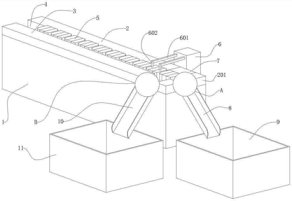
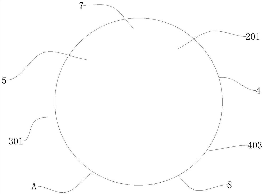
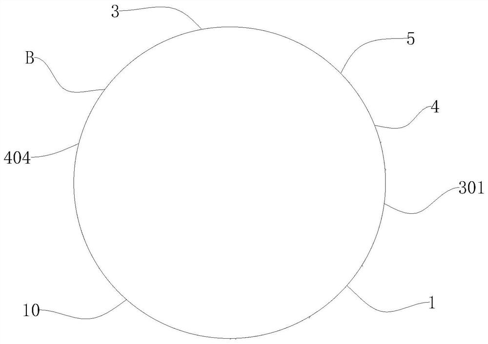
[0037] The present invention provides a patch inductance automatic testing device, comprising a support platform 1, the left and right parts of the rear end of the top side outer surface of the support platform 1 are respectively fixedly installed with a rear stop bar 2 and a rear stop 201, and the support platform 1 The left and right positions of the front end of the top side outer surface of the top side are fi...


PUM


Abstract

The invention provides an automatic testing device for a chip inductor. The device comprises a supporting platform, wherein a rear baffle strip and a rear baffle block are fixedly installed on the left portion and the right portion of the rear end of the outer surface of the top side of the supporting platform respectively, a front baffle strip and a front baffle block are fixedly installed on theleft portion and the right portion of the front end of the outer surface of the top side of the supporting platform respectively, a feeding groove is formed between the outer surface of the front side of the rear baffle strip and the rear baffle block and the outer surface of the rear side of the front baffle strip and the front baffle block; a left conveying belt, a distributing mechanism and aright conveying belt are installed at the bottom end of the feeding groove in a transmission mode from left to right; and a left sliding rail and a right sliding rail are arranged at the upper ends ofthe interiors of the left conveying belt and the right conveying belt correspondingly. According to the automatic testing device, the gravity of an inductor can be used for assisting an air cylinderin achieving classified flexible discharging, continuous vibration on the inductor in the conveying process through a vibration device is avoided, it can be guaranteed that the inductor is not damagedwhile the inductor is normally conveyed, classifying operation is convenient, the number of defective products is reduced, and the product quality is improved.

Description

technical field [0001] The invention relates to the field of processing devices for inductance components, in particular to a chip inductance automatic testing device. Background technique [0002] Inductor (Inductor) is a component that can convert electrical energy into magnetic energy and store it; the structure of an inductor is similar to a transformer, but there is only one winding; the inductor has a certain inductance, it only hinders the change of current; the chip inductor (Chip Inductors), also known as power inductors, high current inductors and surface mount high power inductors, have the characteristics of miniaturization, high quality, high energy storage and low resistance; with the rapid development of power electronics, the functions of electronic products are becoming more and more The stronger it is, the thinner and lighter it is. Therefore, the requirements for chip inductors tend to be miniaturized, high inductance, and low loss. In the process of chip ...

Claims


Application Information

Patent Timeline
IPC IPC(8): B07C5/344B07C5/02B07C5/36
CPCB07C5/02B07C5/344B07C5/36
Inventor 林启升
Owner FENYI XINCHANG ELECTRONICS CO LTD
Learn More