
Double-inerter parallel type four-order vibration reduction structure

A vibration-damping structure, parallel technology, applied in building components, protective buildings/shelters, earthquake-proof, etc., can solve the problems of excessively occupying the interior space of the engine room, the burden of the fan structure, and the large mass of the volume mass.

Active Publication Date: 2021-03-23
NANJING UNIV OF SCI & TECH
View PDF6 Cites 2 Cited by
  • Summary
  • Abstract
  • Description
  • Claims
  • Application Information

AI Technical Summary

Problems solved by technology

[0004] The traditional TMD device is limited to the simple combination of spring, damper and mass block, which has great limitations on the vibration reduction effect of the fan, and its own volume and mass block are too large, thus occupying too much space inside the engine room and affecting the wind turbine. There is a certain burden on the structure

Method used


Image

  • Double-inerter parallel type four-order vibration reduction structure
  • Double-inerter parallel type four-order vibration reduction structure
  • Double-inerter parallel type four-order vibration reduction structure

Examples


Embodiment 1

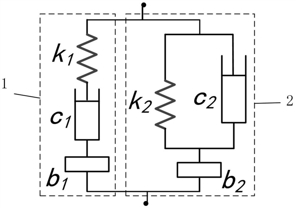
[0023] The first-stage, second-order damping structure 1 includes: a first-stage spring k1, a first-stage inertia b1, and a first-stage damping c1; and the spring k1, inertia b1, and The damping c1 is connected in series;

[0024] The second-stage, second-order damping structure 2 includes: a second-stage spring k2, a second-stage inertia b2, and a second-stage damping c2; and the spring k2 and damping c2 of the second-stage, second-order damping structure 2 After parallel connection, it is connected in series with inertial capacity b2.

Embodiment 2

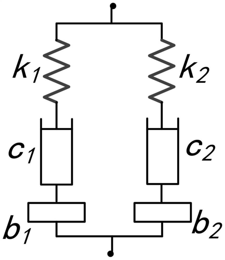
[0026] The first-stage, second-order damping structure 1 includes: a first-stage spring k1, a first-stage inertia b1, and a first-stage damping c1; and the spring k1, inertia b1, and The damping c1 is connected in series;

[0027] The second-stage, second-order damping structure 2 includes: a second-stage spring k2, a second-stage inertia b2, and a second-stage damping c2; and the spring k2, inertia b2 and damping c2 are connected in series.

Embodiment 3

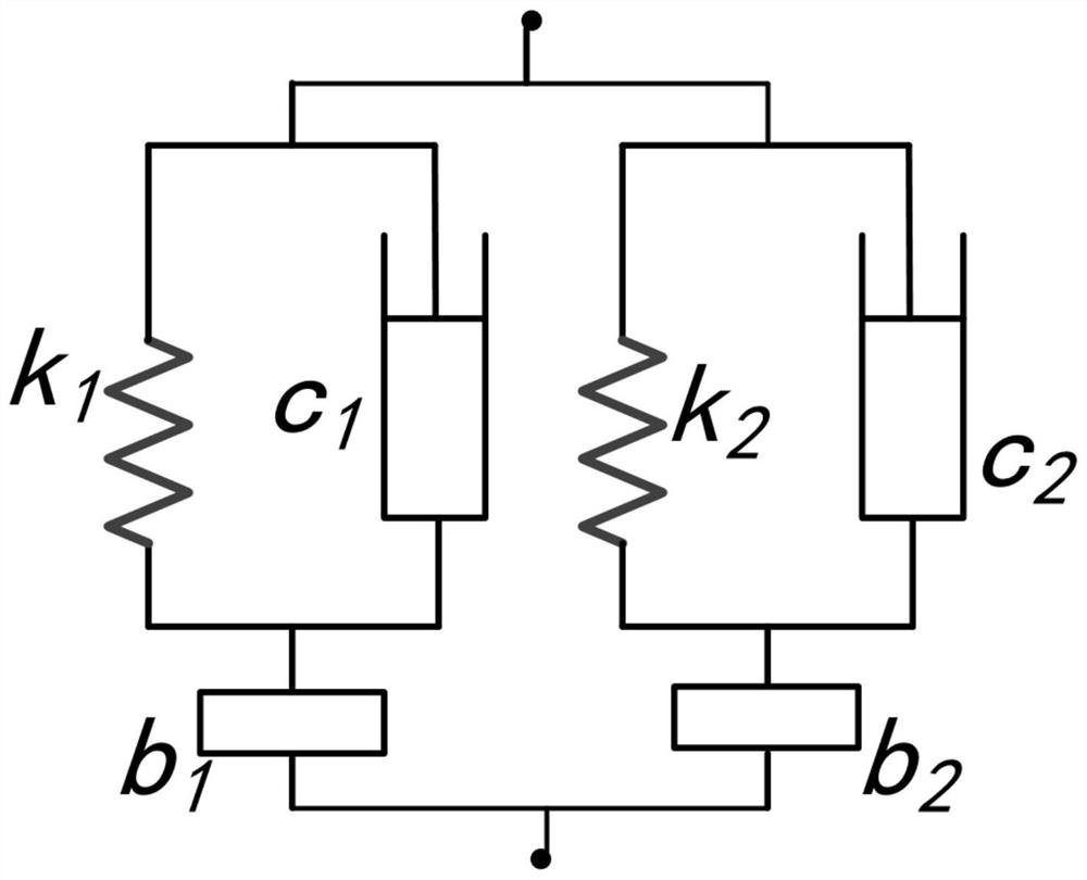
[0029] The first-stage second-order damping structure 1 includes: a first-stage spring k1, a first-stage inertia b1, and a first-stage damping c1; and the spring k1 of the first-stage second-order damping structure 1 is connected in parallel with the damping c1 Afterwards, it is connected in series with the inertial capacity b1;

[0030] The second-stage, second-order damping structure 2 includes: a second-stage spring k2, a second-stage inertia b2, and a second-stage damping c2; and the spring k2 and the damping c2 of the second-stage, second-order damping structure 2 are connected in parallel Afterwards, it is connected in series with the inertial capacity b2.


PUM


Abstract

The invention discloses a double-inerter parallel type four-order vibration reduction structure. The double-inerter parallel type four-order vibration reduction structure comprises two stages of second-order vibration reduction structures, and the two stages of second-order vibration reduction structures are divided into the first-stage second-order vibration reduction structure and the second-stage second-order vibration reduction structure; each of the first-stage second-order vibration reduction structure and the second-stage second-order vibration reduction structure comprises a spring, aninerter and a damper, and the first-stage second-order vibration reduction structure and the second-stage second-order vibration reduction structure are both in a series connection form of the spring, the damper and the inerter or in a series-parallel connection integrated form; and the upper end point and the lower end point of the first-stage second-order vibration reduction structure are connected with the upper end point and the lower end point of the second-stage second-order vibration reduction structure respectively to form a double-inerter parallel type fourth-order vibration reduction structure. According to the double-inerter parallel type four-order vibration reduction structure, the damping ratio and the vibration reduction effect of a fan system can be effectively improved.

Description

technical field [0001] The invention belongs to the technical field of vibration reduction of offshore wind turbines, in particular to a double-inerter parallel fourth-order vibration reduction structure. Background technique [0002] With the gradual increase in the power of a single unit of offshore wind turbines, the quality of the nacelle, impellers, floating platforms, and the height of the tower continue to increase. Because the tower made of flexible materials can greatly reduce the weight of the tower when the height is high, reduce the production cost of the tower, and improve the economic applicability of the wind turbine, so the flexible tower is widely used in large offshore wind turbines. However, the material properties of the flexible tower itself determine that the tower amplitude and platform pitch angle increase under the external wind and wave load conditions of the offshore wind turbine, which affects the reliability of the wind turbine and threatens the ...

Claims


Application Information

Patent Timeline
Patent Type & Authority Applications(China)
IPC IPC(8): E04B1/98E04H9/14B63B35/44F03D80/80
CPCE04H9/14B63B35/44F03D80/88B63B2035/446Y02E10/72
Inventor 陈志强赵爱港
Owner NANJING UNIV OF SCI & TECH
Learn More