
Gas pressurization precision spherical surface forming device and method for lobster eye micropore optical element

A technology of gas pressurization and optical components, which is applied in glass forming, glass reshaping, manufacturing tools, etc. It can solve problems such as uneven expansion of rigid objects, affecting imaging quality, and surface fluctuation deviation.

Active Publication Date: 2021-03-23
NORTH NIGHT VISION TECH
View PDF14 Cites 0 Cited by
  • Summary
  • Abstract
  • Description
  • Claims
  • Application Information

AI Technical Summary

Problems solved by technology

During the precision pressurization, the rigid straight rod is mainly used to connect the mold for pressure loading, but in the actual process, due to the influence of the high temperature environment, the expansion of the rigid object is not uniform, which is easy to cause eccentricity and inclination of the pressure loading, and the inclination during the forming process The upward pressure produces a distortion on the inner channel of the microporous optical element, which affects the final imaging quality
[0004] At the same time, after the final forming of the lens, the rebound phenomenon will occur during the cooling process of the workpiece, which may easily cause a large gap between the final surface shape of the lens after the cold state and the required value. In order to reduce the rebound phenomenon, special treatment is required during the cooling process To ensure surface fluctuation deviation

Method used


Image

  • Gas pressurization precision spherical surface forming device and method for lobster eye micropore optical element
  • Gas pressurization precision spherical surface forming device and method for lobster eye micropore optical element
  • Gas pressurization precision spherical surface forming device and method for lobster eye micropore optical element

Examples


Embodiment Construction

[0033] In order to better understand the technical content of the present invention, specific embodiments are given together with the attached drawings for description as follows.

[0034] Aspects of the invention are described in this disclosure with reference to the accompanying drawings, which show a number of illustrated embodiments. Embodiments of the present disclosure are not necessarily intended to include all aspects of the invention. It should be appreciated that the various concepts and embodiments described above, as well as those described in more detail below, can be implemented in any of numerous ways, since the concepts and embodiments disclosed herein are not limited to any implementation. In addition, some aspects of the present disclosure may be used alone or in any suitable combination with other aspects of the present disclosure.

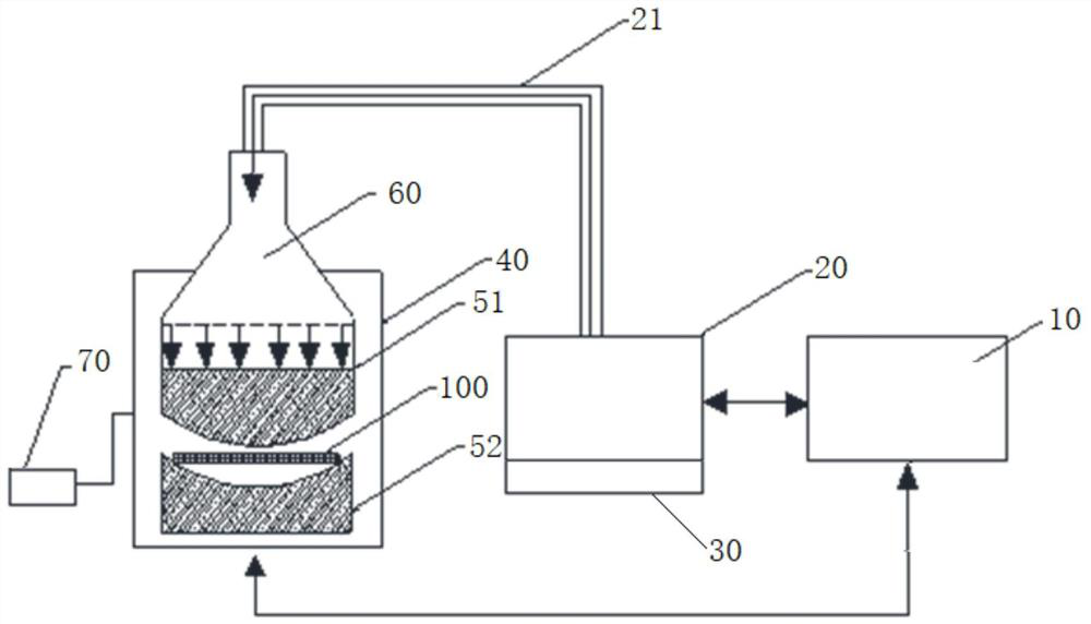
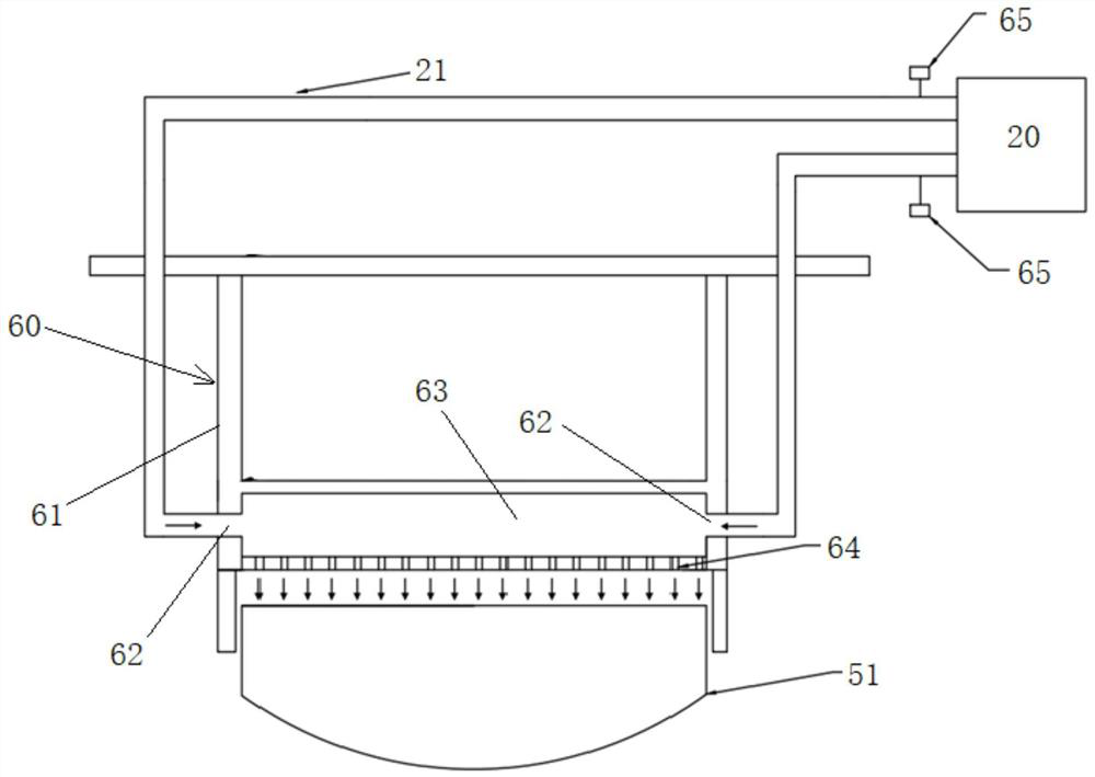
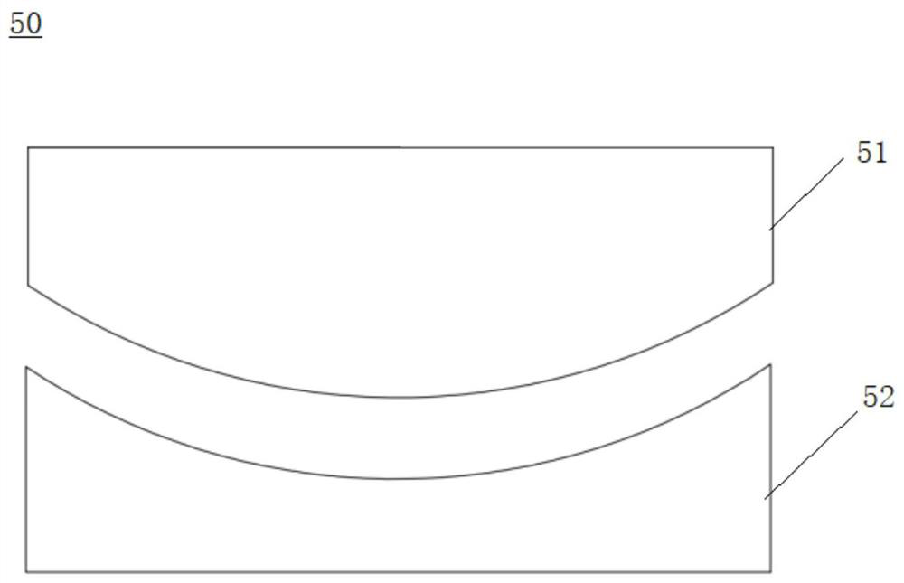
[0035] combine Figure 1-Figure 4 As shown, the gas pressurized precision spherical forming device for square microhole foc...


PUM


Abstract

The invention provides a gas pressurization precision spherical surface forming device and method for a lobster eye micropore optical element. The gas pressurization precision spherical surface forming device comprises a control device, a nitrogen storage device, a pressure controller, a vacuum heating furnace, a spherical surface mold, a gas pressurization device and a vacuum pump. Millions of vertical micropore structures are distributed on the face, opposite to an upper mold of the spherical surface mold, of the gas pressurization device, nitrogen applies pressure to the mold through the vertical micropore structures, and the upper mold is forced to move downwards to enable the lobster eye micropore optical element to be bent and formed. In the manufacturing of the square micropore focusing optical element, a special mold material and a coating technology are adopted to ensure that a square micropore optical element workpiece is not adhered to a mold in a high-temperature sphericalsurface forming process, and gas pressure control is adopted to control the bending of the optical element in the spherical surface forming process; and the springback phenomenon in the process from the viscoelastic body to the elastic body in the cooling process is restrained, and the curvature radius change caused by springback after final forming is reduced.

Description

technical field [0001] The invention relates to the technical field of microhole optical elements, in particular to a square lobster eye microhole focusing optical element, and in particular to a gas pressurized precision spherical forming device and a forming method for square microhole focusing optical elements. Background technique [0002] In the 1970s, Angel first proposed the astronomical telescope model based on the bionic structure of the lobster eye. Since then, the lobster eye optical device has been applied to the field of astronomical observation, and has achieved certain results. Lobster eye optics are typically micro pore optics. Microhole optical element is a kind of grazing incidence optical element, which is composed of millions of square glass microchannels arranged according to specific rules, and can perform X-ray focused imaging through the total reflection of the inner wall of the microchannel. Its unique structure and lightweight advantages have becom...

Claims


Application Information

Patent Timeline
IPC IPC(8): C03B23/00
CPCC03B23/0066Y02P40/57
Inventor 姜博文徐昭金戈顾燕黎龙辉张振李臻吴超廖亦戴周新
Owner NORTH NIGHT VISION TECH
Learn More