
Roller sensor

A technology of sensors and rollers, which is applied in the detection field, can solve the problems of high cost and achieve the effects of ensuring stability, avoiding external electromagnetic interference, and simple structure

Pending Publication Date: 2021-03-23
HANGZHOU HUNING ELEVATOR PARTS CO LTD
View PDF0 Cites 1 Cited by
  • Summary
  • Abstract
  • Description
  • Claims
  • Application Information

AI Technical Summary

Problems solved by technology

It is relatively accurate to set up magnetic strips, gratings, etc. in the elevator shaft to achieve elevator operation detection, but the implementation cost is relatively high

Method used


Image

  • Roller sensor
  • Roller sensor
  • Roller sensor

Examples


Embodiment Construction

[0024] The present invention will be described in detail below in conjunction with the accompanying drawings and specific embodiments.

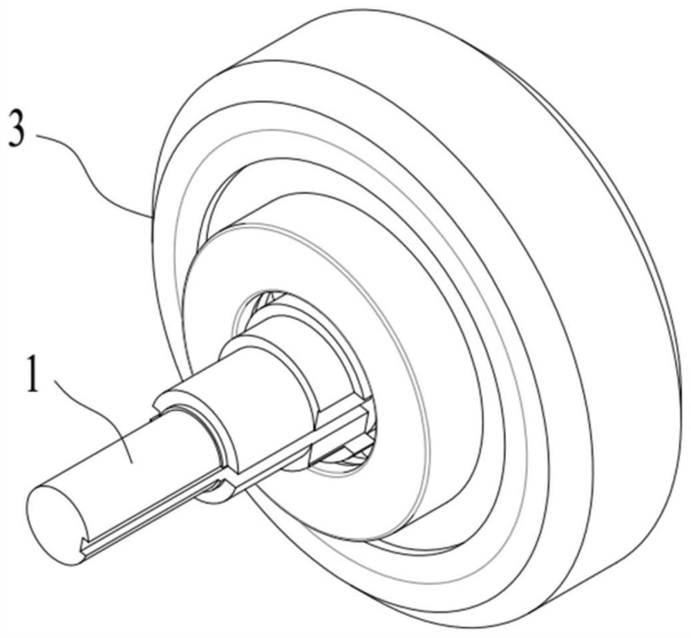
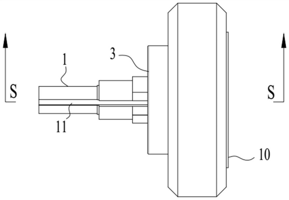
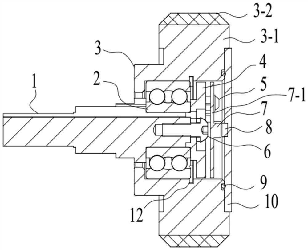
[0025] Such as Figure 1-4 As shown, the roller sensor described in this embodiment includes a roller 3 and a support shaft 1, the first end of the support shaft 1 is connected to the roller 3 through a bearing 2, and the other end is a mounting end; the first end surface of the support shaft 1 is fixed with The circuit board 7-1 is integrated with a magnetic encoder 7 in the center of the circuit board 7-1. The end face of the roller 3 protruding from the first end of the support shaft 1 is sealed and fixed with a cover plate 10, and the cover plate 10 faces the first end of the support shaft 1. A magnetic body 8 facing the magnetic encoder 7 is provided on one side of one end. The roller 3 is in contact with the moving object to be measured or the roller is installed on the moving object to be measured through the bracket, the moving objec...


PUM


Abstract

The invention discloses a roller sensor. The roller sensor comprises a roller and a supporting shaft; a first end of the supporting shaft is connected with the roller through a bearing; a second end is a mounting end; a circuit board is fixedly arranged on the end face of the first end of the supporting shaft; a magnetic encoder is integrated on the circuit board; a cover plate is hermetically andfixedly arranged on the end face, extending out of the first end of the supporting shaft, of the roller; a magnetic body opposite to the magnetic encoder is arranged at one side, facing the first endof the supporting shaft, of the cover plate; and a to-be-measured moving object drives the roller to move, so that the magnetic body moves relative to the magnetic encoder, and measurement is achieved. According to the roller sensor, the roller serves as a transmission medium and makes contact with the to-be-measured moving object or the roller is installed on the moving measured object through asupport, relative rotation is generated between the magnetic body and the magnetic encoder, and the measurement of parameters such as the rotating speed, the displacement, the acceleration and deceleration speed and the vibration is achieved through relative rotation. Therefore, the service life of the magnetic encoder and the circuit board thereof is prolonged, and the roller sensor is simple instructure, convenient to install and suitable for various measurement occasions.

Description

technical field [0001] The invention belongs to the technical field of detection, and in particular relates to a roller sensor. Background technique [0002] The current elevator detects the speed of the car through direct detection by the mechanical speed limiter or by adding an encoder to the mechanical speed limiter or adding an encoder to the traction machine or by setting a magnetic strip or a grating in the elevator shaft. For the mechanical speed limiter, it can only be used to monitor the speed exceeding the preset speed, and has a single function. When adding an encoder to the speed limit or traction machine to detect the speed of the elevator, it is necessary to use the relative slippage between the elevator car and the wire rope to accurately detect the speed in various states. It is relatively accurate to set up magnetic strips, gratings, etc. in the elevator shaft to achieve elevator operation detection, but the implementation cost is relatively high. In order...

Claims


Application Information

Patent Timeline
IPC IPC(8): B66B5/00
CPCB66B5/0087B66B5/0006
Inventor 邹家春姚荣康刘坤李黎
Owner HANGZHOU HUNING ELEVATOR PARTS CO LTD
Learn More