
Direct current peak clipping and valley filling system, device and method

A technology of peak shaving and valley filling, DC load, applied in circuit devices, AC network circuits, AC network load balancing, etc., can solve the problems of complex implementation, rapid increase in power consumption of communication equipment, and large amount of base station renovation works.

Pending Publication Date: 2021-03-19
CHANGSHA ADVANCED MATERIALS IND RES INST CO LTD
View PDF0 Cites 2 Cited by
  • Summary
  • Abstract
  • Description
  • Claims
  • Application Information

AI Technical Summary

Problems solved by technology

With the expansion of the construction scale of communication base stations and the substantial improvement of communication technology performance indicators, the entire industry is facing two main problems: First, the power consumption of communication equipment is increasing rapidly, and the original power supply system of the base station is facing great challenges; It is a base station reconstruction project with a large amount and high cost
[0004] The currently widely used peak-shaving and valley-filling system is based on the grid side, and uses technologies such as bidirectional energy storage inverters, energy management systems, and battery management systems to perform peak-shaving and valley-filling on the AC side. However, the implementation of this system is relatively complicated and the cost is high.

Method used


Image

  • Direct current peak clipping and valley filling system, device and method
  • Direct current peak clipping and valley filling system, device and method
  • Direct current peak clipping and valley filling system, device and method

Examples


Embodiment Construction

[0040] In order to make the purpose, technical solution and advantages of the present application clearer, the present application will be further described in detail below in conjunction with the accompanying drawings and embodiments. It should be understood that the specific embodiments described here are only used to explain the present application, and are not intended to limit the present application.

[0041] In addition, the descriptions such as "first", "second" and so on in the invention are only for the purpose of description, and should not be understood as indicating or implying their relative importance or implicitly indicating the quantity of the indicated technical features. Thus, the features defined as "first" and "second" may explicitly or implicitly include at least one of these features. In the description of the present invention, "plurality" means at least two, such as two, three, etc., unless otherwise specifically defined.

[0042] In the present inven...


PUM


Abstract

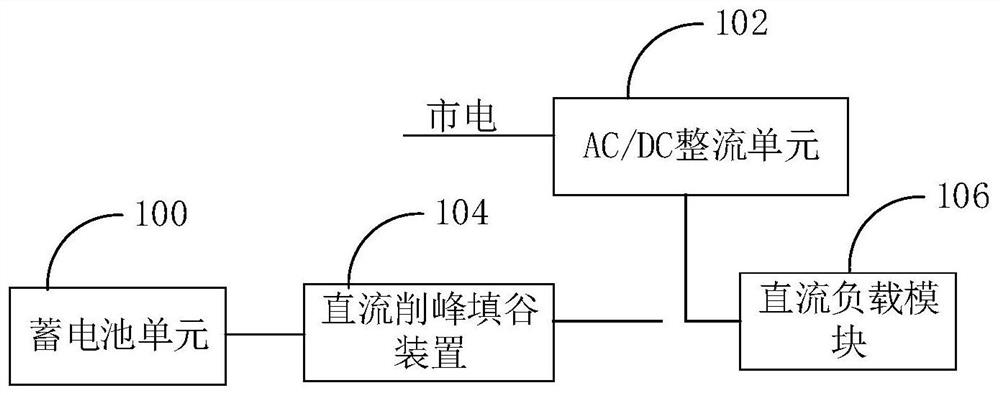
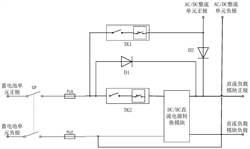
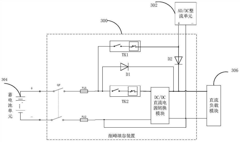
The invention relates to a direct current peak clipping and valley filling system, device and method. The system comprises a storage battery unit, an AC / DC rectifying unit, a direct current peak clipping and valley filling device and a direct current load module. The DC peak clipping and valley filling device controls the time sequence of supplying power to the DC load module by the AC / DC rectification unit, supplying power to the DC load module by the storage battery unit and charging the storage battery unit according to a preset control time sequence. Peak clipping, valley filling, energy storage and consumption reduction are carried out on the direct-current side of the system, only a direct-current line needs to be transformed, an original mains supply alternating-current line is notchanged, operation is easy, cost is low, and installation is convenient. The system can effectively achieve peak clipping and valley filling, peak clipping and valley filling are utilized for peak regulation, and the electric pressure of the mains supply is relieved; and the electricity cost is saved through the peak-valley electricity price difference.

Description

technical field [0001] The present application relates to the technical field of electric power consumption management, in particular to a DC peak-shaving and valley-filling system, device and method. Background technique [0002] In recent years, in order to meet the ever-increasing communication needs and improve service quality, the number of base stations of communication operators has shown a steady growth trend. With the expansion of the construction scale of communication base stations and the substantial improvement of communication technology performance indicators, the entire industry is facing two main problems: First, the power consumption of communication equipment is increasing rapidly, and the original power supply system of the base station is facing great challenges; It is the base station reconstruction project with a large amount of work and high cost. Under the background of the "speed increase and fee reduction" policy, operators need to invest a lot of...

Claims


Application Information

Patent Timeline
Patent Type & Authority Applications(China)
IPC IPC(8): H02J3/32H02J3/00
CPCH02J3/32H02J3/0075
Inventor 谭姣王洋龚云天汪帅吴珊
Owner CHANGSHA ADVANCED MATERIALS IND RES INST CO LTD
Learn More