Novel mechanical automatic lock body structure

An automatic lock and mechanical technology, applied in building locks, building structures, buildings, etc., can solve the problems of large capital occupation and incompatibility, achieve the effect of convenient production and stocking, and reduce the backlog of funds

Pending Publication Date: 2021-03-19
广西鑫扬金属表面处理有限公司
View PDF0 Cites 2 Cited by
  • Summary
  • Abstract
  • Description
  • Claims
  • Application Information

AI Technical Summary

Problems solved by technology

[0002] At this stage, the mechanical automatic lock body usually adopts a gear structure inside, and the lock cylinder equipped with it is a special geared lock cylinder, which is not universal with the standard dial lock cylinder currently on the market. , the factory will produce a series of lock cylinders when producing lock cylinders, which takes up a lot of funds

Method used


Image

  • Novel mechanical automatic lock body structure
  • Novel mechanical automatic lock body structure
  • Novel mechanical automatic lock body structure

Examples


Embodiment 1

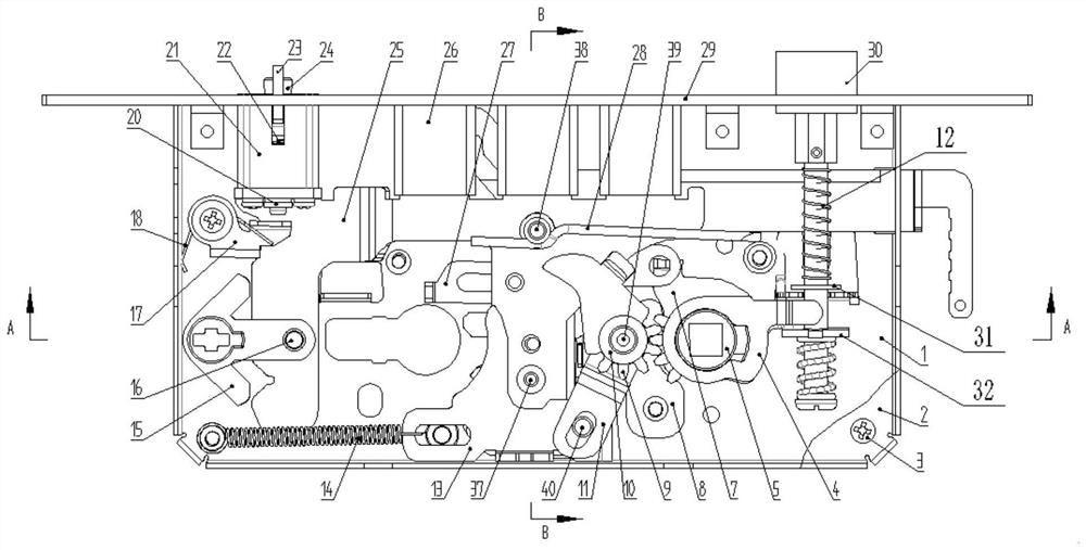
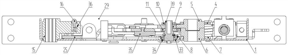
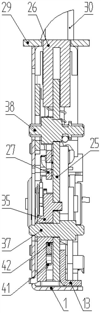
[0034] Such as Figure 1-16 As shown, a novel mechanical automatic lock body structure includes a lock body shell composed of a lower cover plate 1, an upper cover plate 2, an upper cover plate screw 3 and a lock body panel 29, and a main lock is installed in the lock body shell The tongue 26 assembly and the oblique bolt 30 assembly, the main bolt 26 assembly includes the bolt fixing plate 25 and the main bolt 26 anchored on the bolt fixing plate 25 and can be ejected along the lock body panel 29, the bolt fixing plate 25 Such as Figure 5 As shown; the main bolt 26 assembly also includes a deadbolt fixing plate 25 rivets and a main tongue thrust torsion spring 28, and the dead bolt fixing plate 25 rivets are riveted on the dead bolt fixing plate 25, and the main tongue thrust torsion spring 28 is fixed On a stud on the lower cover 1. The deadbolt fixing plate 25 is riveted on the deadbolt fixing plate 25 with a rivet. An annular groove is arranged on the rivet. One arm foo...


PUM


Abstract

The invention discloses a novel mechanical automatic lock body structure, and belongs to the technical field of door locks. The novel mechanical automatic lock body structure comprises a lock body outer shell composed of a lower cover plate, an upper cover plate and a lock body panel, a main spring bolt assembly and an inclined bolt assembly are installed in the lock body outer shell, and the mainspring bolt assembly comprises a spring bolt fixing plate and a main spring bolt which is anchored to the spring bolt fixing plate and can pop up along the lock body panel. A collision wheel spring bolt assembly, a sliding hook plate assembly cooperating with a lock cylinder and used for driving the spring bolt fixing plate to do reciprocating motion in the motion direction of the main spring bolt and a shifting fork assembly used for driving the inclined bolt assembly to do reciprocating motion in the motion direction of the main spring bolt are further mounted in the lock body outer shell.The collision wheel spring bolt assembly is used for driving the spring bolt fixing plate to do reciprocating motion in the motion direction of the main spring bolt. The problem that a standard thumbwheel lock cylinder cannot be used for a mechanical automatic lock body is solved, production and stock of companies are facilitated, and capital overstock is reduced.

Description

technical field [0001] The invention relates to the technical field of door lock products, and more specifically relates to a novel mechanical automatic lock body structure. Background technique [0002] At this stage, the mechanical automatic lock body usually adopts a gear structure inside, and the lock cylinder equipped with it is a special geared lock cylinder, which is not universal with the standard dial lock cylinder currently on the market. , When the factory produces lock cylinders, there will be an extra series of lock cylinders, which takes up a lot of funds. Contents of the invention [0003] The purpose of the present invention is to provide a novel mechanical automatic lock body structure in order to solve the technical problems existing in the background technology. [0004] In order to achieve the above object, the present invention adopts the following technical solutions: [0005] A new type of mechanical automatic lock body structure, including a lock ...

Claims


Application Information

Patent Timeline
IPC IPC(8): E05B63/14E05B15/00E05B15/10
CPCE05B63/146E05B15/00E05B15/10E05B15/108E05B15/102
Inventor 吴泽军
Owner 广西鑫扬金属表面处理有限公司
Why Eureka
Try Eureka