Wood mortise and tenon cutting equipment for building materials

A technology for cutting equipment and wood, applied in the direction of unloading equipment, sawing equipment, sawing components, etc., can solve the problems of inaccurate cutting angle lines, low efficiency, and easy to affect the quality of mortise and tenon joints

Pending Publication Date: 2021-03-19
黄禄珍
View PDF7 Cites 4 Cited by
  • Summary
  • Abstract
  • Description
  • Claims
  • Application Information

AI Technical Summary

Problems solved by technology

[0004] In order to overcome the traditional cutting method relying on manual cutting, the cutting angle line is not accurate, which is easy to affect the quality of mortise and tenon joints. At the same time, manual contact with the cutting machine has the disadvantages of safety hazards and low efficiency. Cutting, one-time cutting, no need to touch the cutting machine manually, to ensure the safety and quality of wood mortise and tenon cutting equipment for building materials

Method used


Image

  • Wood mortise and tenon cutting equipment for building materials
  • Wood mortise and tenon cutting equipment for building materials
  • Wood mortise and tenon cutting equipment for building materials

Examples


Embodiment 1

[0055] Wooden 榫 cutting equipment for building materials, such as figure 1 As shown, a reusing mechanism 3 is coupled between the back and right sides of the bottom left and right sides of the base 1, and the reciprocating mechanism 3 is connected to the reciprocating mechanism 2.

[0056] When the staff needs to make 榫, you need to start the cutting mechanism 2, then start the reciprocating mechanism 3 work to drive the cutting mechanism 2, so that only the staff is placed on the reciprocating mechanism 3, the cutting mechanism 2 moves At the same time, the wood block can be cut, the cutting, stop the cutting mechanism 2 and the reciprocating mechanism 3 work, and then collect the 卯.

Embodiment 2

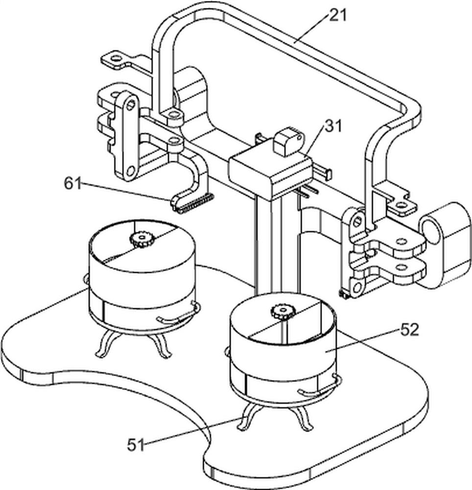
[0058] On the basis of Example 1, such as figure 2 with image 3 As shown, the reciprocating mechanism 3 includes a support frame 31, a slide rail 32, a cylinder 33, and a push block 34, and a support frame 31 is provided on the top of the base 1, and the upper left and right sides of the upper portion of the support frame 31 is connected to the cylinder 33, the retractable of the cylinder 33. The rod is connected to the push block 34, and there is a slide rail 32 between the front side of the left and right sides of the support frame 31, and the slide rail 32 is slidable with the same side push block 34.

[0059] The cutting mechanism 2 includes a mounting frame 21, a high speed motor 22, a first rotating shaft 23, a second rotating shaft 24, a pulley assembly 25, a cut saw blade 26, a tie gear 27, and a third axis 28, and a push block 34 is connected to a installation. The frame 21, the mounting frame 21 is slidably fitted with the same side slide 32, and both sides of the mount...

Embodiment 3

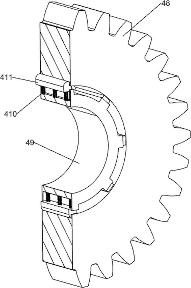
[0062] On the basis of Example 2, such as Figure 4 to 8 As shown, it is also included, and the clamping positioning mechanism 4 includes a clamping positioning mechanism 4 including a bearing housing 41, a fourth axis 42, a first straight gear 43, a tooth column 44, a limit block 45, a cardboard 46, a straight rack 47, the second straight gear 48, the sleeve 49, the first spring 410 and the sliding block 411, the front side of the support frame 31, the bearing housing 41 is provided, and the bearing housing 41 is connected to the fourth axis 42, the fourth axis 42 The first straight gear 43 is connected to the left and right sides, and the upper front side of the upper portion of the support frame 31 is provided with a limit block 45. The sliding type connection is slidable on the limit block 45, and the tooth column 44 is both a straight gear. The 43 meshing, the bottom portion of the tooth column 44 is connected to the card plate 46, and the bottom side of the mounting frame 21 ...


PUM


Abstract

The invention relates to cutting equipment, in particular to wood mortise and tenon cutting equipment for building materials. The wood mortise and tenon cutting equipment for the building materials ismainly provided, precise cutting is achieved through a machine, cutting is completed at a time, hands do not need to make contact with a cutting machine, and safety and quality are guaranteed. The wood mortise and tenon cutting equipment for the building materials comprises a base, and a cutting mechanism; a reciprocating mechanism is connected between the left side and the right side of the topof the base; and the cutting mechanism is connected to the reciprocating mechanism. An air cylinder is arranged, a telescopic rod of the air cylinder stretches out and draws back to drive the cuttingmechanism to reciprocate back and forth so that cutting can be carried out on wood blocks; and through cooperation of a straight rack and a second straight gear, a clamping plate is driven to cut thewood blocks, the state is kept in the cutting process, and cutting is matched.

Description

Technical field [0001] The present invention relates to a cutting apparatus, and more particularly to a wood rubbing device for building materials. Background technique [0002] 榫 卯, is an ancient Chinese architecture, furniture and other instruments. It is also a connection method that combines a concavo-convex portion on both components. It is characterized by not using nails on the object, and uses 加 reinforcing objects, If it is used, the two wooden structures can be strictly detained, and the extent of "seamless" is reached. [0003] Traditional skills cutting must first calculate the data angles of the required 榫 卯, then rely on data manual to perform a size mark on the wooden block, according to the mark using the cut saw blade, this method relies on manual cutting and cutting angles. The line is not accurate, it is easy to influence the quality of the, while manually contacting the cutting machine, there is a safety hazard, and the efficiency is not high. Inventive conte...

Claims


Application Information

Patent Timeline
Patent Type & Authority Applications(China)
IPC IPC(8): B27F1/00B27B5/02B27B5/18B27B5/29B27B29/00B27B31/08B07B13/16
CPCB07B13/16B27B5/02B27B5/18B27B5/187B27B5/29B27B29/00B27B31/08B27F1/00
Inventor 黄禄珍
Owner 黄禄珍
Why Eureka
Try Eureka