Moisture-proof electric power cabinet

A power cabinet and power technology, applied in the direction of electrical components, substation/power distribution device shell, substation/switch layout details, etc., can solve the problem of inconvenient moisture discharge and other problems

Inactive Publication Date: 2021-03-16
公超
View PDF1 Cites 4 Cited by
  • Summary
  • Abstract
  • Description
  • Claims
  • Application Information

AI Technical Summary

Problems solved by technology

[0002] Now there is a patent number: CN202020511856.6 A moisture-proof power cabinet. This utility model discloses a moisture-proof power cabinet, which relates to the technical field of power cabinets. The utility model includes a cabinet body. There is an air vent at the top of the other side of the cabinet, a dust-proof component is provided inside the air intake hole, a second pre-filter plate is fixedly installed inside the air vent hole, and a second pre-filter plate is installed inside the second pre-filter plate. Exhaust fan, the interior of the cabinet is equipped with a number of moisture-proof devices. The moisture-proof device includes two side panels, a placement component and a closing component. There is a T-shaped chute on the inner wall, and the placement component includes a placement board, and a sliding board is fixedly installed on both sides of the placement board. The utility model can fully integrate the moisture inside the cabinet with the upper mesh board by setting a moisture-proof device. The desiccant is in contact with the moisture-proof device, and the permeability effect of the moisture-proof device is good, thereby greatly improving the drying efficiency, but the device is not convenient to discharge the moisture in the cabinet and the room together

Method used


Image

  • Moisture-proof electric power cabinet
  • Moisture-proof electric power cabinet
  • Moisture-proof electric power cabinet

Examples


specific Embodiment approach 1

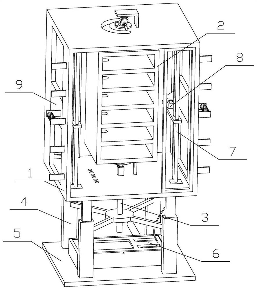
[0032] Combine below Figure 1-11 Describe this embodiment, the present invention relates to the technical field of power cabinets, more specifically a moisture-proof power cabinet, including a storage mechanism 1, a power cabinet mechanism 2, an adjustment device 3, a support mechanism 4, a carrying device 5, a control device 6, and a lifting mechanism 7. The pressing mechanism 8 and the sealing device 9 have the function of discharging the moisture in the cabinet and the room together.

[0033]The said containing mechanism 1 is connected with the electric cabinet mechanism 2, the containing mechanism 1 is connected with the adjusting device 3, the adjusting device 3 is connected with the electric cabinet mechanism 2, the supporting mechanism 4 is fixedly connected with the containing mechanism 1, and the supporting mechanism 4 is threaded with the adjusting device 3 Transmission connection, the supporting mechanism 4 is fixedly connected with the carrying device 5, the carry...

specific Embodiment approach 2

[0035] Combine below Figure 1-11 Describe this embodiment, this embodiment will further explain the first embodiment, the containing mechanism 1 includes a container 1-1, a hinged door 1-2, a chute 1-3, a fixed piece 1-4, a limit piece 1 -5, L-shaped plate 1-6, vertical column 1-7, pressure column 1-8 and drainage hole 1-9, the front and rear ends of the container 1-1 are hingedly connected with hinged door 1-2, container 1 The left and right ends of -1 are all provided with chute 1-3, and the inside of chute 1-3 is fixedly connected with rotating rod, and the left and right ends of containing box 1-1 are fixedly connected with a plurality of fixed pieces 1-4 symmetrically, and containing box The upper part of 1-1 is fixedly connected with the limiting plate 1-5, the upper part of the container 1-1 is fixedly connected with an L-shaped plate 1-6, and the inside of the left and right ends of the container 1-1 is fixedly connected with a vertical column 1-7, The upper side of ...

specific Embodiment approach 3

[0037] Combine below Figure 1-11 Describe this embodiment, this embodiment will further explain the second embodiment, the power cabinet mechanism 2 includes a power cabinet body 2-1, a cabinet groove 2-2, a swivel base 2-3, a fixed block 2-4 and a round Disk 2-5, the power cabinet 2-1 is provided with a plurality of cabinet grooves 2-2 running through the front and rear ends, the upper part of the power cabinet 2-1 is fixedly connected with the swivel base 2-3, and the upper part of the swivel base 2-3 The fixed block 2-4 is fixedly connected, the lower part of the power cabinet body 2-1 is fixedly connected with a disc 2-5, and the lower part of the disc 2-5 is uniformly fixedly connected with multiple blocks I in the circumferential direction, and the power cabinet body 2- 1 is provided with threading holes running through the upper and lower ends, the swivel base 2-3 is hingedly connected with the top of the container 1-1, and a torsion spring is sleeved between the upper...


PUM


Abstract

The invention relates to the technical field of electric power cabinets, in particular to a moisture-proof electric power cabinet which comprises a containing mechanism, an electric power cabinet mechanism, an adjusting device, a supporting mechanism, a bearing device, a control device, lifting mechanisms, pressing mechanisms and sealing devices. The containing mechanism is connected with the electric power cabinet mechanism, the containing meachanism is connected with the adjusting device, the adjusting device is connected with the electric power cabinet mechanism, the supporting mechanism isfixedly connected with the containing mechanism, the supporting mechanism is in threaded transmission connection with the adjusting device, the supporting mechanism is fixedly connected with the bearing device, the bearing device is hinged to the control device, the control device is fixedly connected with the containing mechanism, the containing mechanism is symmetrically connected with the twolifting mechanisms, the two lifting mechanisms are fixedly connected with pressing mechanisms, the pressing mechanisms are matched with sealing devices, the sealing devices are connected with the containing mechanism, and the number of the sealing devices is multiple. The cabinet has the function of exhausting moisture in the cabinet and moisture in a room at the same time.

Description

technical field [0001] The invention relates to the technical field of power cabinets, and more specifically relates to a moisture-proof power cabinet. Background technique [0002] Now there is a patent number: CN202020511856.6 A moisture-proof power cabinet. This utility model discloses a moisture-proof power cabinet, which relates to the technical field of power cabinets. The utility model includes a cabinet body. There is an air vent at the top of the other side of the cabinet, a dust-proof component is provided inside the air intake hole, a second pre-filter plate is fixedly installed inside the air vent hole, and a second pre-filter plate is installed inside the second pre-filter plate. Exhaust fan, the interior of the cabinet is equipped with a number of moisture-proof devices. The moisture-proof device includes two side panels, a placement component and a closing component. There is a T-shaped chute on the inner wall, and the placement component includes a placement...

Claims


Application Information

Patent Timeline
IPC IPC(8): H02B1/28H02B1/56H02B1/30
CPCH02B1/28H02B1/30H02B1/565
Inventor 公超
Owner 公超
Why Eureka
Try Eureka