
Perpendicular prefabricated member conveying device for assembled building construction

A technology for conveying devices and prefabricated parts, which is applied in the direction of conveyors, transportation and packaging, etc., which can solve the problems of low safety in hoisting and transportation, transportation of building prefabricated parts, and reduced construction efficiency, so as to achieve high conveying efficiency and high overall conveying safety , to avoid the effect of falling

Inactive Publication Date: 2021-03-12
邓学兰
View PDF0 Cites 4 Cited by
  • Summary
  • Abstract
  • Description
  • Claims
  • Application Information

AI Technical Summary

Problems solved by technology

[0003] The applicant found that when the current prefabricated building is constructed, the prefabricated building parts need to be hoisted one by one to the building floor by the set crane, and moved to the right position for connection and installation, and a building construction site is subject to Due to the influence of space constraints, the number of cranes generally installed is limited, so the efficiency of hoisting and vertically conveying prefabricated building parts is affected. The weight and volume of the parts are large, and the stability of the hoisting connection needs to be ensured when the crane is hoisted, but there is still a risk of hoisting or collision during the hoisting process, resulting in low overall hoisting and transportation safety

Method used


Image

  • Perpendicular prefabricated member conveying device for assembled building construction
  • Perpendicular prefabricated member conveying device for assembled building construction
  • Perpendicular prefabricated member conveying device for assembled building construction

Examples


Embodiment Construction

[0036] In order to make the purpose, technical solutions and advantages of the present disclosure clearer, the present disclosure will be further described in detail below in conjunction with specific embodiments.

[0037]It should be noted that, unless otherwise defined, the technical terms or scientific terms used in one or more embodiments of the present specification shall have ordinary meanings understood by those skilled in the art to which the present disclosure belongs. "First", "second" and similar words used in one or more embodiments of the present specification do not indicate any order, quantity or importance, but are only used to distinguish different components. "Comprising" or "comprising" and similar words mean that the elements or items appearing before the word include the elements or items listed after the word and their equivalents, without excluding other elements or items. Words such as "connected" or "connected" are not limited to physical or mechanical...


PUM


Abstract

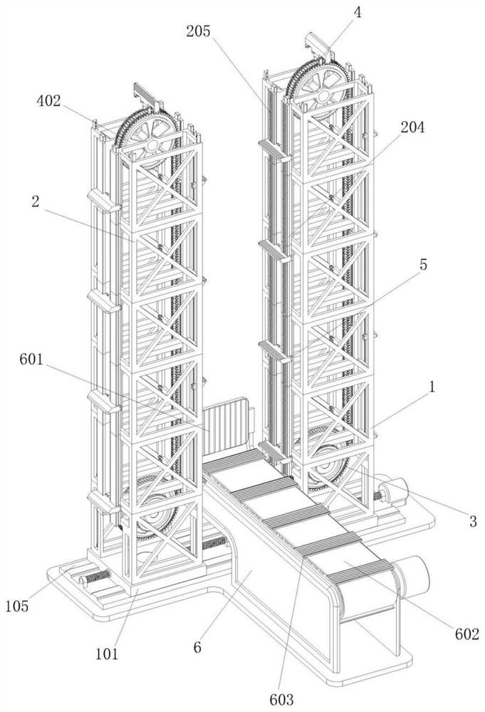
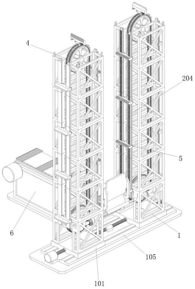
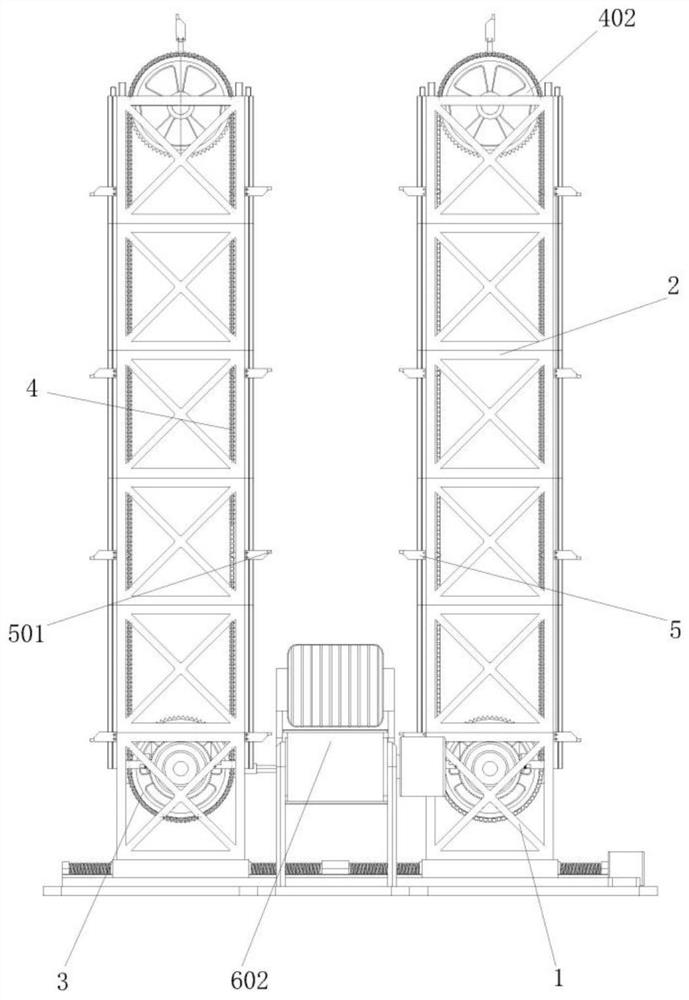
One or more embodiments of the description provide a perpendicular prefabricated member conveying device for assembled building construction. The device comprises sleeve type brackets, traction gears,traction chains and carrying locking seats, wherein each sleeve type bracket consists of a plurality of split brackets arranged vertically and perpendicularly; the traction gears are arranged on thetop of the sleeve type brackets; the traction chains are arranged on the outer side of the traction gear; the carrying locking seats are uniformly arranged on the outer side of the traction chain, andhorizontal carrying plates are arranged on the outer sides of the carrying locking seats. By arranging the traction chain structures on the symmetrically arranged sleeve type brackets, the carrying locking seats and the horizontal carrying plates are uniformly and symmetrically arranged on each traction chain. By moving the traction chains to drive all the horizontal carrying plates to move perpendicularly and circularly along the sleeve type brackets, each pair of horizontal carrying plates can carry a prefabricated member to move upward along the traction chain, so that a plurality of concrete prefabricated members can be conveyed successively at the same time, and the conveying efficiency is higher.

Description

technical field [0001] One or more embodiments of this specification relate to the technical field of prefabricated building construction, and in particular to a vertical conveying device for prefabricated parts used in prefabricated building construction. Background technique [0002] Prefabricated building refers to the transfer of a large number of on-site operations in the traditional construction method to the factory, where the building components and accessories are processed and manufactured in the factory, such as floors, wall panels, stairs, balconies, etc., and transported to the construction site. The connection method is assembled and installed on site. Prefabricated buildings mainly include prefabricated concrete structures, steel structures, modern wooden structures, etc., because standardized design, factory production, assembly construction, information management, intelligent Modernized application is a representative of modern industrialized production met...

Claims


Application Information

Patent Timeline
IPC IPC(8): B65G17/12B65G17/34
CPCB65G17/123B65G17/34
Inventor 邓学兰
Owner 邓学兰
Learn More