Dry and wet garbage separation sanitation box

A sanitation box and garbage technology, applied in the field of sanitation boxes, can solve problems such as lack of storage

Inactive Publication Date: 2021-03-12
湖南盛瑞环保科技有限公司
View PDF1 Cites 1 Cited by
  • Summary
  • Abstract
  • Description
  • Claims
  • Application Information

AI Technical Summary

Problems solved by technology

There are certain defects in the design of this patent. The patent designs the overall sanitation box as a pressing and crushing device, which itself does not have the function of storage, which is counterproductive to the sanitation box.

Method used


Image

  • Dry and wet garbage separation sanitation box
  • Dry and wet garbage separation sanitation box
  • Dry and wet garbage separation sanitation box

Examples


Embodiment 1

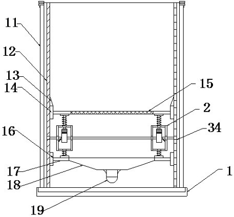
[0024] see Figure 1~3 , a dry and wet garbage separation sanitation box, including a box body 1, the box body 1 includes an outer box body frame 11 and an inner loading frame 12, the inner cavity of the inner loading frame 12 is provided with a sundry carrying cavity 13, the Sliding rails 14 are arranged on the sides of the inner cavity of the sundries carrying chamber 13, and a water filter screen 15 is arranged between the slide rails 14 on the left and right sides. 14, the bottom of the filter screen 15 is also provided with a filtrate collection cavity bucket 18, and the filtrate collection cavity bucket 18 is arranged directly below the space position of the water filter screen plate 15, and the two sides of the filtrate collection cavity bucket 18 A side edge plate 17 is provided at the end, and a fixed piece 16 is arranged on the inner wall of the box body 1. The side edge plate 17 and the fixed piece 16 are fixedly installed, and the bottom of the filtrate collection ...

Embodiment 2

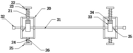
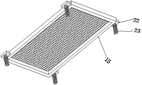
[0028] see figure 2 , this embodiment is a further optimization of Embodiment 1. On the basis of it, a transverse strut 31 is arranged between the medium vibrating frame 20 on the same side, and the two ends of the transverse strut 31 are fixedly installed on the box by fixing bolts 32. In the inner cavity of the body 1, a toggle block 33 is arranged on the transverse strut 31, and the toggle block 33 is respectively located in the inner cavity of the corresponding medium vibration frame 20. The upper edge of the toggle block 33 is provided with a corrugated block 34, and the bottom end of the upper edge support rod 21 is inserted into the corrugated block 34, and a built-in Buffer spring 35.

[0029] For the medium vibrating frame 20, the application design is provided with a transverse strut 31 between the medium vibrating frames 20, and a toggle block 33 is set in the inner cavity of the medium vibrating frame 20, through the corrugated structure on the toggle block 33 an...


PUM


Abstract

The invention relates to the technical field of sanitation boxes, and particularly relates to a dry and wet garbage separation sanitation box. The dry and wet garbage separation sanitation box comprises a box body, wherein a screening frame is arranged between a filtrate collecting cavity hopper and a water filtering net plate; the screening frame comprises medium vibration frames; the four mediumvibration frames are arranged at the four corners; upper edge supporting rods are arranged at the tops of the medium vibration frames; frame erecting plates are arranged at the four corners of the water filtering net plate; buffer springs are arranged on the bottom planes of the frame erecting plates; the tops of the upper edge supporting rods are erected in notches of the frame erecting plates but are not fixedly installed; the buffer springs are connected between the upper planes of the frame erecting plates and the medium vibration frames; lower edge supporting rods are arranged at the bottoms of the medium vibration frames; the lower edge supporting rods are telescopic movable rods; a fixed bottom block is arranged on the edge of the filtrate collecting cavity hopper; the bottom endsof the telescopic movable rods are fixedly installed on the fixed bottom block; and the telescopic movable rods are wound with the buffer springs. According to the dry and wet garbage separation sanitation box, the technical effect of triple vibration is achieved, flowing of the auxiliary retained water liquid is improved, and the purpose of solid-liquid separation is achieved.

Description

technical field [0001] The invention relates to the technical field of sanitation boxes, in particular to a sanitation box for separating dry and wet garbage. Background technique [0002] As a kind of garbage storage device, sanitation boxes are spread all over the city, which is convenient for people to solve the garbage on hand, and also convenient for the city to maintain a better city appearance. A common sanitation bin has two garbage collection bins, one for recyclables and the other for other waste. Sanitation workers regularly clean the sanitation boxes and transport the garbage to the garbage treatment plant. However, because many people do not sort garbage when throwing garbage, the two kinds of garbage are mixed. At the same time, people still have some dry and wet mixed garbage in their lives, such as unfinished beverage bottles, lunch boxes with residual soup, and unfinished fruits. If this kind of garbage is not disposed of in a timely manner after being th...

Claims


Application Information

Patent Timeline
Patent Type & Authority Applications(China)
IPC IPC(8): B65F1/00B65F1/14
CPCB65F1/006B65F1/14B65F2210/176Y02W30/10
Inventor 匡小勇
Owner 湖南盛瑞环保科技有限公司
Why Eureka
Try Eureka