Subway signal transmission and protection system
A technology of signal transmission and protection system, applied in the field of rail transit
- Summary
- Abstract
- Description
- Claims
- Application Information
AI Technical Summary
Problems solved by technology
Method used
Image
Examples
Embodiment 1
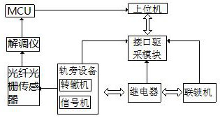
[0035] combine Figure 1-4 , a subway signal transmission and protection system, characterized in that it includes a host computer and trackside equipment, the trackside equipment is connected to the trackside controller of the host computer through a relay and an interlocking machine, the trackside equipment, the relay and the interlocking machine are connected to the upper computer through the corresponding interface driving module in the wayside controller. The wayside equipment includes a switch machine and a signal machine. The wayside controller includes a main control module and a The signal machine control module, the switch machine control module, the communication module and the I / O acquisition module connected to the module, the relay is used to realize the light of the signal machine, the control of the switch machine, the acquisition of the track occupancy status, and set the disconnection fault. The locking machine is connected with the switch machine and signal ...
Embodiment 2
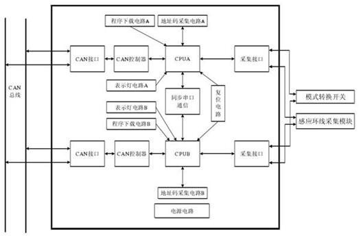
[0040] On the basis of Example 1, combined with image 3 , the switch machine is used as the key signal equipment for turning the switch, and its working status is directly related to the safety and transportation efficiency of the tram during operation. Code / type code acquisition circuit, display circuit, indicator light circuit, program download circuit, reset circuit, power supply circuit and other hardware circuits. The module circuit is designed in strict accordance with the principles of modularization and strong and weak current isolation.
[0041] The switch machine control module adopts closed-loop control technology, electromagnetic compatibility technology, isolation technology, control circuit double-break technology and completely independent "two out of two" functional structure for safety protection.
Embodiment 3
[0043] On the basis of Example 1, combined with Figure 4 , the signal light control module includes 3 sets of MCU circuits, 2 sets of relay action drive circuits, 2 sets of relay state acquisition circuits, 2 sets of lighting current detection circuits, 3 sets of CAN communication circuits, 2 sets of address code acquisition circuits, indicating light circuits, Program download circuit, reset circuit and power supply circuit.
[0044] The signal light control module adopts a completely independent two-out-of-two structure to realize safety control. The CAN communication circuit is used to realize the transmission of information such as signal light control commands, lighting status and fault alarms between the interlock control host and the signal light module. The control MCU circuit is responsible for the entire module. The core logic operation of the system, according to the interlock command issued by the interlock control host, acts on the related relays symmetrically se...
PUM
 Abstract
Description
Claims
Application Information
 - R&D
- Intellectual Property
- Life Sciences
- Materials
- Tech Scout
- Unparalleled Data Quality
- Higher Quality Content
- 60% Fewer Hallucinations
Browse by: Latest US Patents, China's latest patents, Technical Efficacy Thesaurus, Application Domain, Technology Topic, Popular Technical Reports.
© 2025 PatSnap. All rights reserved.Legal|Privacy policy|Modern Slavery Act Transparency Statement|Sitemap|About US| Contact US: help@patsnap.com


