Cloth perforating machine

A punching machine and fabric technology, applied in the textile field, can solve the problems of affecting the punching accuracy, increasing labor costs, affecting the continuous operation of the machine, etc., achieving the effect of simple structure and improving production efficiency

Inactive Publication Date: 2021-03-12
陈米胜
View PDF0 Cites 0 Cited by
  • Summary
  • Abstract
  • Description
  • Claims
  • Application Information

AI Technical Summary

Problems solved by technology

[0002] With the development of the economy and the improvement of people's living standards, there are more and more styles of clothes, and the update speed of clothes is getting faster and faster. Therefore, the requirements for the production speed of clothes are getting faster and faster. When making clothes, it is necessary to The cloth is punched so that the process can go smoothly, but the traditional punching often relies on manual punching, the punching accuracy cannot be guaranteed, and it is time-consuming and labor-intensive, which increases the labor cost. The quality of the finished product is also different, and the existing punching machine cannot guarantee the positioning of the cloth during punching, and the cloth is offset during the punching process, which affects the punching accuracy. At the same time, due to the material of the cloth, the waste often adheres On the tool, it affects the continuous operation of the machine. Therefore, it is urgent to design a punching machine that ensures the drilling accuracy and ensures that the machine can be efficiently and continuously carried out.

Method used


Image

  • Cloth perforating machine
  • Cloth perforating machine
  • Cloth perforating machine

Examples


Embodiment Construction

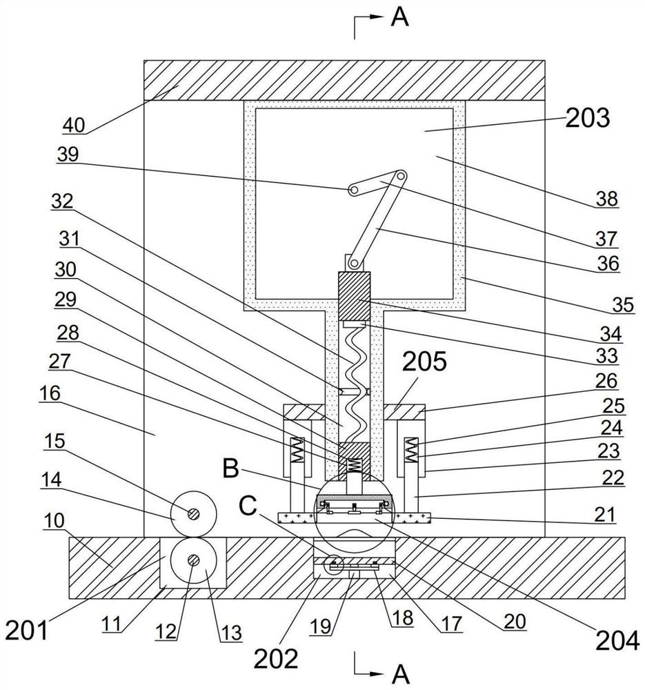
[0021] Such as figure 1As shown, a fabric punching machine includes a body 10, two first support plates 16 are fixedly fixed on the front and back sides of the upper side of the body 10, and second support plates are fixedly arranged on the upper ends of the two first support plates 16. plate 40, the body 10 is provided with a feed trough 11, the feed chute 11 is provided with a feed device 201 for conveying cloth, the body 10 is provided with an auxiliary punching groove 17, and the auxiliary punching The hole slot 17 is located on the right side of the feeding slot 11, the auxiliary punching slot 17 is provided with a discharge device 202 for discharging waste, and the lower side of the second support plate 40 is fixedly provided with a punching case 35, A power space 38 is provided in the perforated housing 35 , and a first chute 30 with an open lower end is also provided in the perforated housing 35 , the first chute 30 is located at the lower side of the power space 38 , ...


PUM


Abstract

The invention discloses a cloth perforating machine. The machine comprises a machine body, two first supporting plates are fixedly arranged on the upper side face of the machine body in a front-back symmetrical manner, second supporting plates are fixedly arranged on the upper end faces of the two first supporting plates, a feeding groove is formed in the machine body, and a feeding device used for conveying cloth is arranged in the feeding groove; and an auxiliary perforating groove is formed in the machine body, the auxiliary perforating groove is located at the right side of the feeding groove, a discharging device used for discharging waste is arranged in the auxiliary perforating groove, the cloth is perforated, meanwhile, the position needing to be perforated is positioned in the perforating process, the situation that the perforating position is incorrect and the perforating precision is not enough due to the fact that the cloth is displaced by friction force between the cloth and a cutter during perforating is prevented, meanwhile, the perforating device is cleaned, the waste is prevented from being attached to the perforating device and affecting continuous operation of perforating work, the machine can operate continuously, and the production efficiency is improved.

Description

technical field [0001] The invention belongs to the textile field, in particular to a cloth punching machine. Background technique [0002] With the development of the economy and the improvement of people's living standards, there are more and more styles of clothes, and the update speed of clothes is getting faster and faster. Therefore, the requirements for the production speed of clothes are getting faster and faster. When making clothes, it is necessary to The cloth is punched so that the process can go smoothly, but the traditional punching often relies on manual punching, the punching accuracy cannot be guaranteed, and it is time-consuming and labor-intensive, which increases the labor cost. The quality of the finished product is also different, and the existing punching machine cannot guarantee the positioning of the cloth during punching, and the cloth is offset during the punching process, which affects the punching accuracy. At the same time, due to the material o...

Claims


Application Information

Patent Timeline
IPC IPC(8): B26F1/16B26D7/02B26D7/18
CPCB26D7/025B26D7/18B26F1/16
Inventor 陈米胜
Owner 陈米胜
Why Eureka
Try Eureka