
Camera visual axis disturbance measuring equipment and method based on inertial reference unit

An inertial reference, camera boresight technology, applied in the field of high-resolution space optical remote sensing, can solve the problems of affecting boresight disturbance measurement accuracy, affecting boresight disturbance measurement effect, poor boresight disturbance measurement accuracy, etc., so as to ensure correlation measurement. Accuracy and boresight disturbance measurement accuracy, ensure high collimation, and ensure the effect of high energy concentration

Active Publication Date: 2021-03-09
BEIJING RES INST OF SPATIAL MECHANICAL & ELECTRICAL TECH
View PDF6 Cites 2 Cited by
  • Summary
  • Abstract
  • Description
  • Claims
  • Application Information

AI Technical Summary

Problems solved by technology

[0005] 1) The traditional boresight perturbation measurement method based on ground object images is highly dependent on the texture information of ground objects and meteorological conditions. The contrast of local objects is poor, and when there is cloud and fog interference, the accuracy of boresight disturbance measurement is poor or even Not working, poor usability;
[0006] 2) The traditional boresight perturbation measurement method based on ground object images, for the push-broom imaging space camera, the signal-to-noise ratio of the boresight perturbation measurement detector is very low, which affects the measurement accuracy of the boresight perturbation;
[0007] 3) The ground object images obtained by the push-broom imaging space camera and the boresight disturbance measurement detector are constantly changing, and the correlation is poor, which affects the measurement effect of the boresight disturbance;

Method used


Image

  • Camera visual axis disturbance measuring equipment and method based on inertial reference unit
  • Camera visual axis disturbance measuring equipment and method based on inertial reference unit
  • Camera visual axis disturbance measuring equipment and method based on inertial reference unit

Examples


Embodiment

[0076] For a space camera with a focal length f of 20 m and an imaging detector pixel of 7 microns, its angular resolution is 0.35 μrad. In order to achieve a camera boresight disturbance measurement accuracy better than 0.1 times the angular resolution, the angular displacement measurement accuracy of the inertial reference unit should be better than 0.01μrad, the angular stability between the inertial reference units of the light-emitting component should be better than 0.01μrad, and the reflection of the light-guiding component should be better than 0.01μrad. The angle stability of the mirror is better than 0.01μrad; the spot centroid extraction accuracy is better than 0.05 pixel; the positional stability of the spot recording focal plane and imaging detector is better than 0.03 pixel.

[0077] If the frequency of the boresight disturbance of the camera is 20Hz, the measurement frequency of the boresight disturbance should generally be ≥ 200Hz.

[0078] The focal length of ...


PUM

PropertyMeasurementUnit
Widthaaaaaaaaaa

Abstract

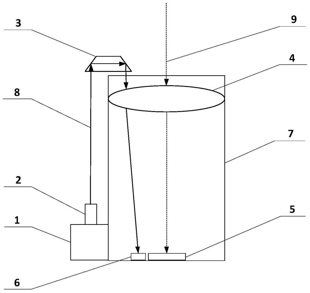
The invention discloses camera visual axis disturbance measuring equipment and method based on an inertial reference unit. The measuring equipment is composed of a high-precision inertial reference unit and an associated measuring unit. The inertial reference unit generally adopts a fiber-optic gyroscope, an angular displacement sensor and the like, and can accurately measure absolute angular displacement information at a mounting position; the associated measuring unit can accurately measure the relative angular displacement information between the visual axis of the camera and the inertial reference unit; the absolute angular displacement information of the camera, namely the visual axis disturbance quantity of the camera, can be obtained by combining the two sets of angular displacementinformation, the information can be used for image motion blur compensation, and the imaging quality of the long-focus space camera is improved.

Description

technical field [0001] The invention relates to the technical field of high-resolution space optical remote sensing, in particular to a camera visual axis disturbance measurement device and method based on an inertial reference unit. Background technique [0002] The high-resolution space camera has the characteristics of long focal length, and a slight perturbation of the visual axis will also cause significant image blur and affect the imaging quality. In order to eliminate the influence of the boresight disturbance of the space camera on the image quality, it is necessary to accurately measure the boresight disturbance of the space camera, and realize the compensation and correction of the boresight disturbance by means of image processing or optical-mechanical image stabilization. [0003] The traditional boresight disturbance measurement method mainly adopts the boresight disturbance measurement method based on the observation target or auxiliary beacon image, that is, ...

Claims


Application Information

Patent Timeline
IPC IPC(8): G01M11/02
CPCG01M11/02G01M11/0207
Inventor 程少园孙世君阮宁娟孙德伟于艳波杨沐
Owner BEIJING RES INST OF SPATIAL MECHANICAL & ELECTRICAL TECH
Learn More