
Face recognition equipment mounting bracket applicable to multiple scenes

A technology for face recognition equipment and mounting brackets, which is applied to mechanical equipment, machine platforms/brackets, supporting machines, etc., and can solve the problems of face recognition equipment being unable to effectively switch between use scenarios, single applicable scenarios, and non-adjustable installation methods

Pending Publication Date: 2021-03-09
DELI GROUP CO LTD
View PDF0 Cites 0 Cited by
  • Summary
  • Abstract
  • Description
  • Claims
  • Application Information

AI Technical Summary

Problems solved by technology

[0002] The use scenarios of face recognition devices in the prior art mainly include wall-mounted type and gate type. The wall-mounted type is mainly installed on the wall or on the door frame, and the gate type is installed on the gate through a pole. The recognition device itself will have a mounting frame connected to the main body. The mounting frame is mainly fixed by screws, and then the face recognition device is fixed on the mounting frame. The mounting frame in the prior art is mainly a Y-shaped bracket structure or a flat structure. It is fixed by two horizontal screws and one vertical screw. Due to different manufacturers and different usage scenarios, the size of the mounting frame is different. Because the communication port of the face recognition device is the same, the actual device can be used on the wall and the gate. The scenes are switched between each other, but due to the limitation of the equipment bracket, the face recognition equipment cannot effectively switch the use scene, and the installation method cannot be adjusted according to the actual use scene, thereby reducing the applicable performance of its use and resulting in a single applicable scene, which also limits product sales channels

Method used


Image

  • Face recognition equipment mounting bracket applicable to multiple scenes
  • Face recognition equipment mounting bracket applicable to multiple scenes
  • Face recognition equipment mounting bracket applicable to multiple scenes

Examples


Embodiment Construction

[0026] The present invention will be described in further detail below in conjunction with the accompanying drawings.

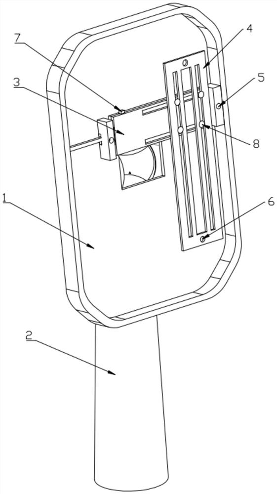
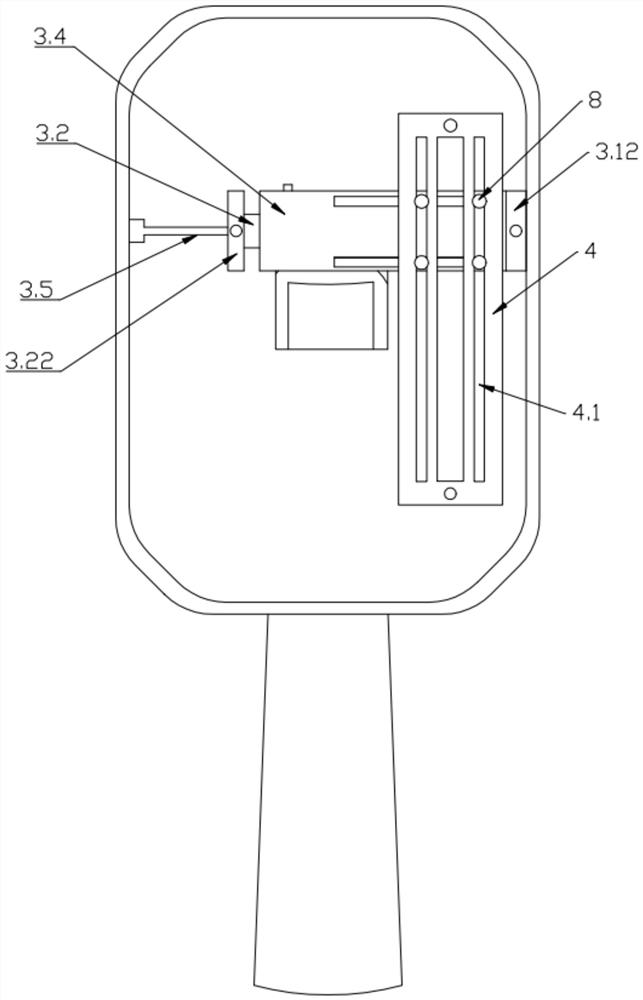
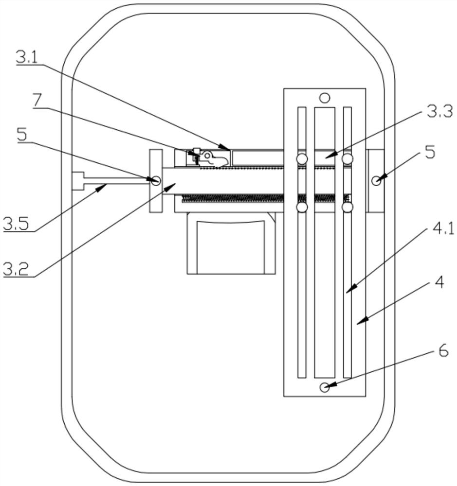
[0027] In conjunction with the accompanying drawings, the present invention discloses a mounting bracket for installing face recognition equipment. The face recognition equipment in the prior art is equipped with a bracket, and the bracket of the present application is connected to the self-contained bracket. Then install the face recognition device on the self-contained bracket. The self-contained bracket mainly includes two horizontal screw holes and one screw hole at the bottom. The wall-mounted face recognition device directly fixes the self-contained bracket on the wall or On the door frame, the structure is a thin plate. The built-in bracket of the gate-type face recognition device is mainly a bracket with a wire barrel, which can be erected. The general shape is similar to the shape of this application, that is to say, the wall-mounted The installation...


PUM


Abstract

The invention discloses a face recognition equipment mounting bracket applicable to multiple scenes, which comprises a back plate (1) and a wiring cylinder (2) connected with the back plate (1), and is characterized in that an upper bracket (3) and a lower bracket (4) are arranged on the back plate (1) and are provided with upper threaded holes (5) and lower threaded holes (6), and the positions of the upper threaded holes (5) in the upper bracket (3) can be adjusted horizontally; and the positions of the lower threaded holes (6) in the lower bracket (4) can be horizontally and vertically adjusted. Compared with the prior art, the face recognition equipment mounting bracket applicable to multiple scenes provided by the invention has the advantages that wall-mounted face recognition equipment is finally installed on a gate machine to be used through the bracket, the use scenes of the wall-mounted face recognition equipment can be effectively switched, the application scenes of the facerecognition equipment are enhanced, and the sales channels of products are broadened.

Description

technical field [0001] The invention relates to the technical field of mounting brackets for face recognition devices, in particular to mounting brackets for face recognition devices that can be adapted to various installation scenarios. Background technique [0002] The use scenarios of face recognition devices in the prior art mainly include wall-mounted type and gate type. The wall-mounted type is mainly installed on the wall or on the door frame, and the gate type is installed on the gate through a pole. The identification device itself will have a mounting frame connected to the main body. The mounting frame is mainly fixed by screws, and then the face recognition device is fixed on the mounting frame. The mounting frame in the prior art is mainly a Y-shaped bracket structure or a flat structure. It is fixed by two horizontal screws and one vertical screw. Due to different manufacturers and different usage scenarios, the size of the mounting frame is different. Because ...

Claims


Application Information

Patent Timeline
Patent Type & Authority Applications(China)
IPC IPC(8): F16M11/04F16M11/18
CPCF16M11/043F16M11/18
Inventor 胡亮亮张鑫郭海超
Owner DELI GROUP CO LTD
Learn More