Rescue evacuation facility on fabricated railway bridge and construction method

A railway bridge, prefabricated technology, applied in bridge construction, bridges, bridge parts, etc., can solve the problems of difficult to control the vibrating quality of concrete pouring, poor stability, large scale of cast-in-place supports, etc.

Pending Publication Date: 2021-03-09
CHINA RAILWAY DESIGN GRP CO LTD
View PDF0 Cites 0 Cited by
  • Summary
  • Abstract
  • Description
  • Claims
  • Application Information

AI Technical Summary

Problems solved by technology

[0004] The problem to be solved by the present invention is to provide a rescue and evacuation facility and construction method on a prefabricated railway bridge, which is especially suitable for solving

Method used


Image

  • Rescue evacuation facility on fabricated railway bridge and construction method
  • Rescue evacuation facility on fabricated railway bridge and construction method
  • Rescue evacuation facility on fabricated railway bridge and construction method

Examples


Embodiment 1

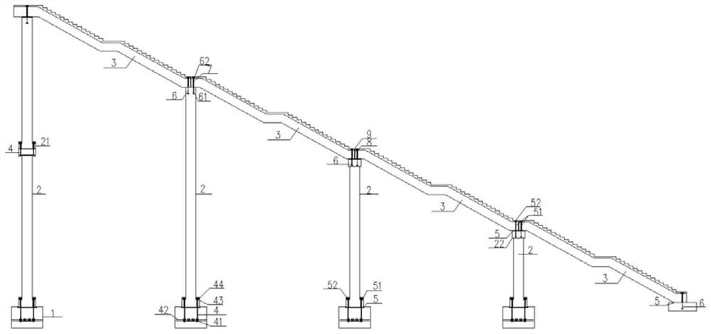
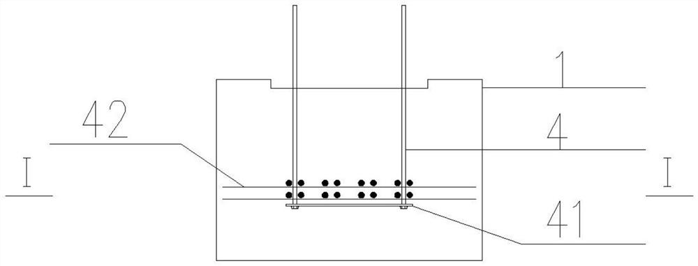
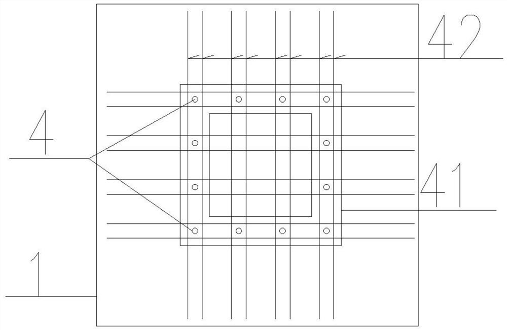
[0039] Such as Figure 1-6 As shown, the present invention is an assembled railway bridge rescue evacuation facility and a construction method, including the base body 1, the column 2 and the stairs 3, the base body 1 is a rectangular structure, and the connection key is disposed in the base body 1 4, and the connection key 4 is free ends the upper surface of the base 1, and the bottom portion is provided with a connecting post 21, and a plurality of pre-projected holes 7 are provided on the connecting post 21, and the reserved hole 7 and the connection key within the base body 1 are provided. 4 One-one, the top of the column 2 is provided with a shear key 6, and the top of the shear key 6 is free ends the top surface of the column 2, and the stairs 3 are disposed on the top of the column 2 and the stairs 3 is provided with a reserve hole 7. The upper free end of the shear key 6 corresponds to the reserved hole 7 at the bottom of the stairs 3, and the upper surface of the base body...

Embodiment 2

[0053] Such as Figure 7 In still, the beam 22 is the L-type structure, and there is a shear key 6 in which the stair 3 is the interleave structure, and the lower end is connected to the beam 22, and the beam 22 is provided with a reserved hole 7. The stairs 3 are laid in the horizontal region of the beam 22, and the fill seam 8 and the sealant 9 are provided in the vertical region of the stair 3 and the beam 22, and the shear bond 6 penetrates into the reserved hole 7.


PUM


Abstract

The invention provides a rescue evacuation facility on fabricated railway bridge and a construction method. The rescue evacuation facility comprises a foundation body, stand columns and stairs, connecting columns are arranged at the bottoms of the stand columns, preformed holes correspond to connecting keys in the foundation body in a one-to-one mode, the stairs are arranged at the tops of the stand columns, and preformed holes are formed in the two sides of the bottoms of the stairs; shear key top free ends are arrange in a one-to-one corresponding manner with the bottoms of the stairs; Splicing seams are formed between the upper surface of the foundation body and the bottoms of the stand columns, the upper surface of the foundation body and the bottoms of the stand columns are spliced and connected with the connecting keys through the splicing seams, splicing seams are formed between the tops of the stand columns and the bottoms of the stairs, and the tops of the stand columns and the bottoms of the stairs are spliced and connected with the shear keys through the splicing seams; and grouting materials are arranged in the preformed holes of the connecting columns provided with theconnecting keys. The stand columns in an evacuation passage are high in height and small in size, the stand columns are prefabricated in factories and hoisted and assembled on site, supports do not need to be erected, and safety is high; stairs in the evacuation channel are of a continuous structure, prefabricated stairs are adopted, hole-by-hole hoisting and erection construction are conducted,and the site construction time is obviously shortened.

Description

Technical field [0001] The present invention belongs to the field of railway bridges, in particular, involving a rescue evacuation facility and construction method on assembled railway bridges. Background technique [0002] The rescue evacuation facility on the railway bridge is an important part of the railway disaster prevention and rescue security system. When there is an earthquake, the fire is used to quickly evacuate the passengers when there is an emergency situation in the bridge, and partly part of the maintenance and repair function, everyday In railway maintenance, the staff can be set at about 3km along the line direction by evacuation facilities. [0003] The rescue evacuation facility on the railway bridge is composed of foundation, column, beam and stairs. Currently, there is currently in-place construction, there is a problem of difficulty in casting bracket templates, poor concrete pouring, long construction period; for some approach to business line or level roa...

Claims


Application Information

Patent Timeline
IPC IPC(8): E01D19/00E04F11/00E04F11/02
CPCE01D19/00E04F11/00E04F11/02
Inventor 苏伟张帅牛远志李伟超
Owner CHINA RAILWAY DESIGN GRP CO LTD
Why Eureka
Try Eureka