
Dry film preparation equipment

A film and dry-type technology, applied in the field of dry-type film preparation equipment, can solve the problems of unfavorable operator work process, cumbersome and complicated, and reduce the practicability of the device, so as to increase work efficiency and safety, avoid excessive operation difficulty, The effect of increasing work efficiency

Inactive Publication Date: 2021-03-05
无锡泽远医疗科技有限公司
View PDF0 Cites 0 Cited by
  • Summary
  • Abstract
  • Description
  • Claims
  • Application Information

AI Technical Summary

Problems solved by technology

[0004] 1. The existing device will transport the dry film when it is working, and will stack the dry film together in turn, making the dry film difficult to be picked up by the operator. The dry film is stacked together, which greatly affects the operator's perception The observation of the dry film is not conducive to the rapid observation of the dry film by the operator, which increases the time for the operator to observe the dry film, which is not conducive to the practicability of the device, and the existing device has no supporting device for supporting the work of the dry film , reducing the efficiency of the device
[0005] 2. After the existing device prints out the dry film, the operator must hold the dry film to observe the dry film. This process is very cumbersome and complicated, and the operator needs to align the dry film with the light source and hold the head up for a long time. It will cause soreness in the neck and shoulders of the operator, which is not conducive to the operator's long-term work process and reduces the practicability of the device

Method used


Image

  • Dry film preparation equipment
  • Dry film preparation equipment
  • Dry film preparation equipment

Examples


Embodiment Construction

[0025] The following will clearly and completely describe the technical solutions in the embodiments of the present invention with reference to the accompanying drawings in the embodiments of the present invention. Obviously, the described embodiments are only some, not all, embodiments of the present invention. Based on the embodiments of the present invention, all other embodiments obtained by persons of ordinary skill in the art without making creative efforts belong to the protection scope of the present invention.

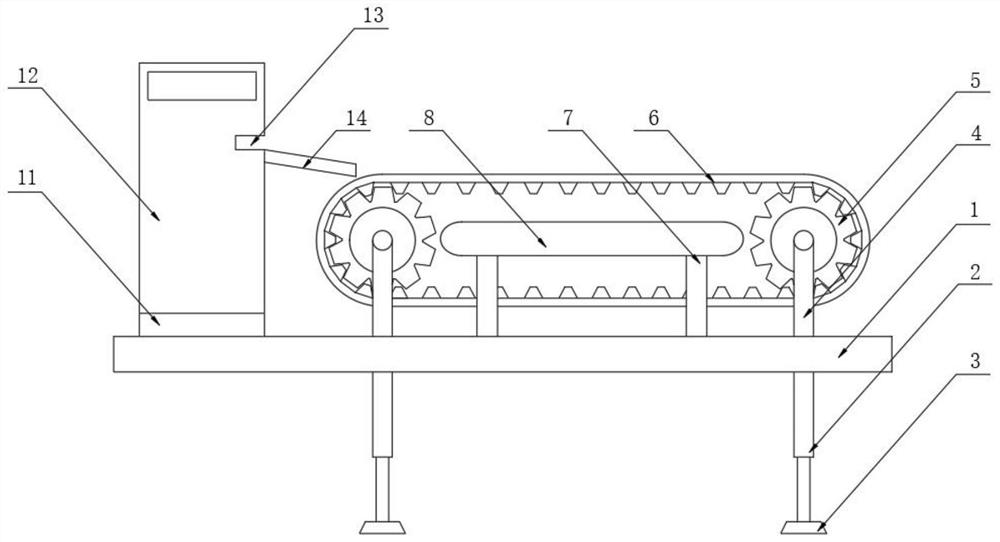
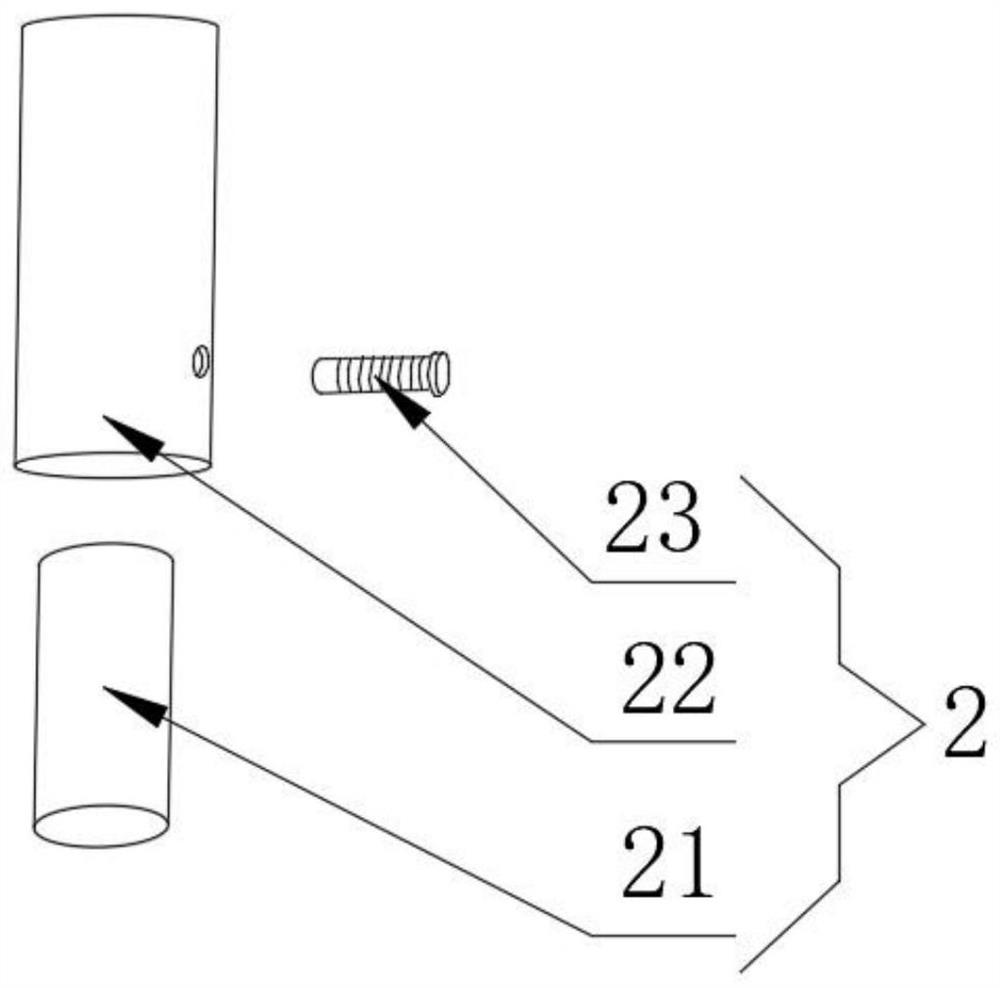
[0026] as attached Figure 1-5 The shown dry film preparation equipment includes a workbench 1, a support device 2 is fixedly installed at the bottom of the workbench 1, a fixed seat 11 is fixedly installed at the top left end of the workbench 1, and a fixed seat 11 is fixedly installed on the top surface of the fixed seat 11. There is a printing and imaging device 12, the right side surface of the printing and imaging device 12 is provided with a film outlet ...


PUM


Abstract

The invention discloses dry film preparation equipment, and particularly relates to the field of transportation device. The dry film preparation equipment comprises a workbench, wherein a supporting device is fixedly installed at the bottom end of the workbench, a fixing base is fixedly installed at the top end of the left end of the workbench, printing imaging equipment is fixedly installed on the top surface of the fixing base, a film outlet is formed in the right side surface of the printing imaging equipment, a connecting plate is fixedly installed on the right side of the film outlet, anda base is fixedly connected to the bottom end of the supporting device. By arranging the connecting plate and the conveying belt, when dry films are conveyed out from a conveying port after printingwork is completed, the dry films slide to the surface of the conveying belt through the connecting plate, then the dry films slide to the surface of the conveying belt from the surface of the connecting plate one by one, the conveying belt sequentially arranges a plurality of dry films on the surface of the conveying belt, so that the time for operators to operate and observe the dry films is shortened, and the working efficiency of the device is improved.

Description

technical field [0001] The invention relates to the technical field of transportation equipment, more specifically, the invention relates to a dry film preparation equipment. Background technique [0002] Dry film refers to the medium used to carry the graphic information of medical images. Dry film is divided into two categories according to the imaging principle: one is chemical imaging film, non-chemical imaging film, and the dry film is imaged in the machine. Finally, the dry film will be sent out from the mouth of the machine. Usually, a doctor holds the dry film at the light source and carefully observes the imaging on the surface of the dry film, so as to diagnose and treat the patient's illness. [0003] However, there are still some disadvantages in its actual use, such as: [0004] 1. The existing device will transport the dry film when it is working, and will stack the dry film together in turn, making the dry film difficult to be picked up by the operator. The d...

Claims


Application Information

Patent Timeline
Patent Type & Authority Applications(China)
IPC IPC(8): G02B27/02B65G47/34
CPCB65G47/34G02B27/024
Inventor 庄重
Owner 无锡泽远医疗科技有限公司
Learn More