
Jumper wire test system and jumper wire simulation test tool

A simulation test and jumper wire technology, applied in the field of vehicles, can solve the problems of time-consuming and labor-intensive, waste of space, collection and arrangement of unfavorable parameters, etc., and achieve the effect of shortening the verification period, simplifying the inspection operation, and improving the test efficiency.

Active Publication Date: 2021-03-05
CRRC HANGZHOU CO LTD
View PDF6 Cites 0 Cited by
  • Summary
  • Abstract
  • Description
  • Claims
  • Application Information

AI Technical Summary

Problems solved by technology

The disadvantage of this verification method is that the verification can only be realized after the production of the whole vehicle is completed. Before the verification, the whole vehicle needs to be connected and connected. The verification period is long, and if the verification effect of some cables is not satisfactory, a large number of finished cables will be scrapped. Will cause a large quality loss, so the timeliness of the verification results is very low
As for the existing tooling simulation method, because the tooling completely simulates the vehicle structure, the structure is only designed according to one type of vehicle, which cannot be applied to subway vehicles of other structures, so it is not universal; and it occupies a large area, wastes space, and is time-consuming Labor-intensive, low verification efficiency, and not conducive to the collection and arrangement of parameters

Method used


Image

  • Jumper wire test system and jumper wire simulation test tool
  • Jumper wire test system and jumper wire simulation test tool
  • Jumper wire test system and jumper wire simulation test tool

Examples


Embodiment Construction

[0030] The following will clearly and completely describe the technical solutions in the embodiments of the present invention with reference to the accompanying drawings in the embodiments of the present invention. Obviously, the described embodiments are only some, not all, embodiments of the present invention. Based on the embodiments of the present invention, all other embodiments obtained by persons of ordinary skill in the art without making creative efforts belong to the protection scope of the present invention.

[0031] In order to enable those skilled in the art to better understand the solution of the present invention, the present invention will be further described in detail below in conjunction with the accompanying drawings and specific embodiments.

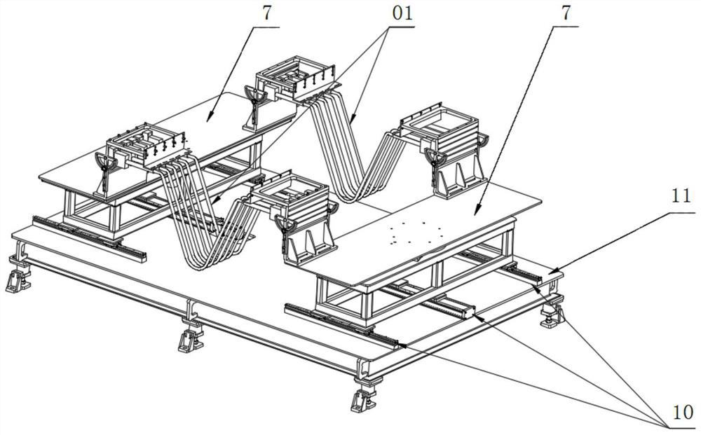
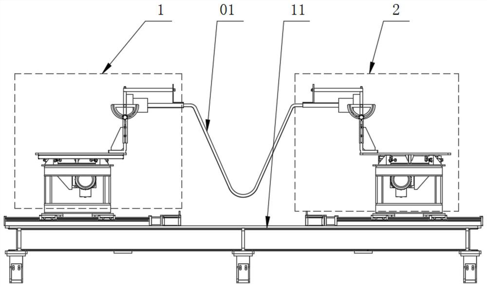
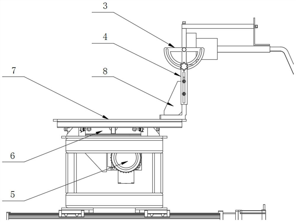
[0032] Please refer to Figure 1 to Figure 5 , figure 1 Schematic diagram of the structure of the jumper simulation test tool provided by the embodiment of the present invention; figure 2 for figure 1 main view ...


PUM


Abstract

The invention discloses a jumper wire test system and a jumper wire simulation test tool. The jumper wire simulation test tool comprises a first test bench and a second test bench. Both the first testbed and the second test bed are provided with wire harness interfaces and rotary tables used for driving the wire harness interfaces to automatically swing. The wire harness interface of the first test bench and the wire harness interface of the second test bench are used for connecting a jumper wire to be tested. The first test bench and the second test bench are both provided with adjusting clamping pieces used for adjusting the distance and / or inclination angle of the wire harness interfaces. The jumper wire simulation test tool not only can simulate the connection of the jumper wire to betested between adjacent carriages, but also can adjust the position state of the jumper wire to be tested and simulate the connection of the jumper wire to be tested between the carriages of different types of vehicles through the rotary tables and the adjusting clamping pieces, thereby checking whether the jumper wire to be tested can meet the use requirements or not. According to the jumper wire simulation test tool, the operation can be simplified, the test efficiency is improved, the universality is improved, and the test cost is reduced.

Description

technical field [0001] The invention relates to the field of vehicles, in particular to a jumper simulation test tool. It also relates to a jumper test system, including the above-mentioned jumper simulation test tool. Background technique [0002] The subway vehicle jumper cable is one of the important electrical components used to realize the electrical connection of adjacent vehicles. When the vehicle travels through the curved track, the jumper cables will also be stretched or compressed to varying degrees as the adjacent cars rotate relative to each other. If the cable length is not selected properly, it may even cause the cable to be pulled and disconnected, or the cable is too compressed to scratch the cable due to contact with the track. If such cables are damaged, it will have a great impact on driving safety, so it can be seen that the appropriate cable length is extremely important for the smooth operation of the vehicle. [0003] At present, the length of jump...

Claims


Application Information

Patent Timeline
Patent Type & Authority Applications(China)
IPC IPC(8): G01M17/08
CPCG01M17/08
Inventor 徐凤林王耀春方骅蔡洋涛杨富贵于磊
Owner CRRC HANGZHOU CO LTD
Learn More