Brushless motor

A brushless motor and vibration damping mechanism technology, applied in the direction of electrical components, electromechanical devices, electric components, etc., can solve the problems of affecting work efficiency, force fracture damage, poor ventilation and heat dissipation, etc., to ensure normal operation and reduce damage probability, the effect of improving the efficiency of use

Active Publication Date: 2021-03-02
湖南运弘达电机股份有限公司
View PDF10 Cites 3 Cited by
  • Summary
  • Abstract
  • Description
  • Claims
  • Application Information

AI Technical Summary

Problems solved by technology

[0003] In the process of realizing the present invention, the inventor found that at least the following problems in the prior art have not been solved: 1. Before using the brushless motor, it is necessary to fix the brushless motor and the mounting surface, and the fixing method is divided into two types: , the first one is to fix the installation panel and the motor casing on the output shaft side of the brushless motor with bolts, the second one is to use an external mounting bracket to wrap the brushless motor as a whole and install it at the designated position, while for the first one The installation method, the brushless motor installed in this way will produce a certain vibration amplitude when it works, because the installation and fixing force point of the motor is mainly between the shell and the installation panel, and it is mainly connected and fixed by bolts, so long-term Use and frequent vibration will lead to uneven force on the force point, and excessive force will cause breakage and damage, which will affect the normal operation of the equipment. At the same time, for the second installation method, although the motor can be fixed bett...

Method used


Image

  • Brushless motor
  • Brushless motor
  • Brushless motor

Examples


Embodiment Construction

[0035] The technical solutions in the embodiments of the present invention will be clearly and completely described below in conjunction with the accompanying drawings in the embodiments of the present invention. Apparently, the described embodiments are only some, not all, embodiments of the present invention. Based on the embodiments of the present invention, all other embodiments obtained by persons of ordinary skill in the art without making creative efforts belong to the protection scope of the present invention.

[0036] see Figure 1 to Figure 8 , the present invention provides a technical solution:

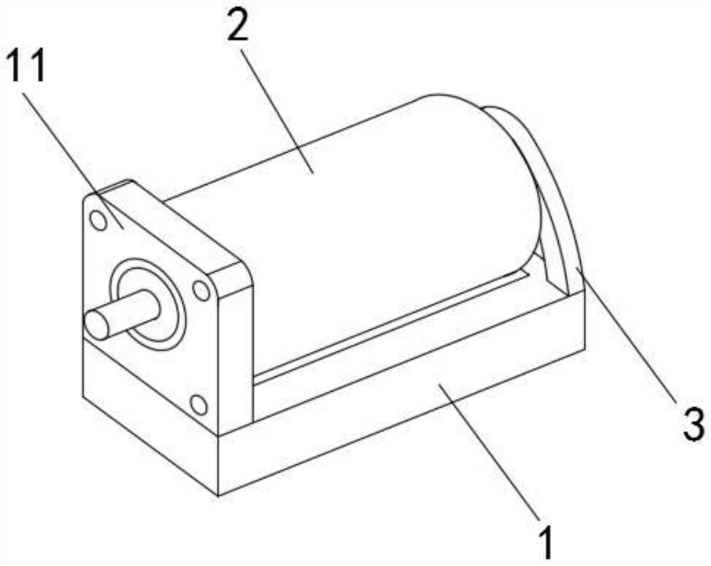
[0037] A brushless motor, comprising a base 1 and a front panel 11 forming a fixed seat body with an L-shaped cross-section, the outer surface of the upper end of the base 1 is provided with a motor body 2, and the inner middle of the front panel 11 is provided with a placement slot , and the output shaft of the motor body 2 extends through the front panel 11 through the ...


PUM


Abstract

A brushless motor disclosed by the invention comprises a fixed base main body of an L-shaped cross section, wherein the fixed base main body is formed by a pedestal and a front panel, a motor main body is arranged on the outer surface of the upper end of the pedestal, a placement groove is formed in the middle of the interior of the front panel, an output shaft of the motor main body penetrates through the front panel through the placement groove and extends to the left side of the front panel, the side, away from the front panel, of the outer surface of the upper end of the pedestal is fixedly connected with a rear fixing mechanism, and the outer surface of the upper end of the base is of an arc-shaped structure. According to the brushless motor, the motor is supported and fixed through the design of the fixed base main body, the motor is suitable for being installed and fixed in multiple modes, the motor is protected to a certain extent, the damage probability of a traditional installation mode is reduced, meanwhile, a vibration reduction mechanism is additionally arranged, vibration reduction and noise reduction can be well conducted on vibration generated in the operation process of the motor, so that normal operation of equipment is guaranteed, compared with a traditional vibration reduction structure, the structure can facilitate air ventilation and heat dissipation of the motor, and the use efficiency of the device is effectively improved.

Description

technical field [0001] The invention relates to the technical field of brushless motors, in particular to a brushless motor. Background technique [0002] The brushless DC motor is composed of the main body of the motor and the driver. It is a typical mechatronics product. Since the brushless DC motor operates in a self-controlled manner, it will not be in the rotor like a synchronous motor that is started under heavy load under variable frequency speed regulation. Adding an additional starting winding on it will not cause oscillation and out-of-step when the load changes suddenly. [0003] In the process of realizing the present invention, the inventor found that at least the following problems in the prior art have not been solved: 1. Before using the brushless motor, it is necessary to fix the brushless motor and the mounting surface, and the fixing method is divided into two types: , the first one is to fix the installation panel and the motor casing on the output shaft...

Claims


Application Information

Patent Timeline
IPC IPC(8): H02K5/24H02K5/20H02K5/04B08B1/00B08B1/02B08B15/04
CPCB08B1/005B08B1/006B08B1/02B08B15/04H02K5/04H02K5/20H02K5/24
Inventor 李乐东
Owner 湖南运弘达电机股份有限公司
Why Eureka
Try Eureka