Protection device of visual inspection system

A technology for visual inspection and protection devices, which is applied to parts of TV systems, measuring devices, parts of color TVs, etc., can solve problems such as difficult to change, complex mechanical structure, and ineffective cleaning blocks due to aging, so as to improve the performance of the device. , the effect of eliminating the force of the collision

Pending Publication Date: 2021-03-02
HUAQING INTELLIGENT TECH (SUZHOU) CO LTD
View PDF1 Cites 0 Cited by
  • Summary
  • Abstract
  • Description
  • Claims
  • Application Information

AI Technical Summary

Problems solved by technology

However, since the belt conveyor operates outdoors in the open air, its mechanical structure is complex and difficult to change. All kinds of dust, water mist, and large pieces of coal falling from the belt conveyor belt seriously affect the accuracy of the visual inspection system, so how to overcome the harsh environment on site? The impact on visual detection is the key to improving the detection accuracy of belt tearing; as the protection device of a kind of visual detection system disclosed by the invention of CN205643140U, although it effectively reduces the various dusts, The interference of water mist and falling coal on the visual inspection system can also ensure that the camera of the visual inspection system is not corroded by the on-site environment, but it does not solve the problem that the cleaning block will age and lose its efficacy after long-term use. Therefore, we propose a Protection device for visual inspection system

Method used


Image

  • Protection device of visual inspection system
  • Protection device of visual inspection system
  • Protection device of visual inspection system

Examples


Embodiment Construction

[0023] In order to make the technical means, creative features, achievement goals and effects realized by the present invention easy to understand, the present invention will be further described below in conjunction with specific embodiments, but the following embodiments are only preferred embodiments of the present invention, not all. Based on the examples in the implementation manner, other examples obtained by those skilled in the art without creative work shall fall within the protection scope of the present invention. The experimental methods in the following examples are conventional methods unless otherwise specified, and the materials, reagents, etc. used in the following examples can be obtained from commercial sources unless otherwise specified.

[0024] Example:

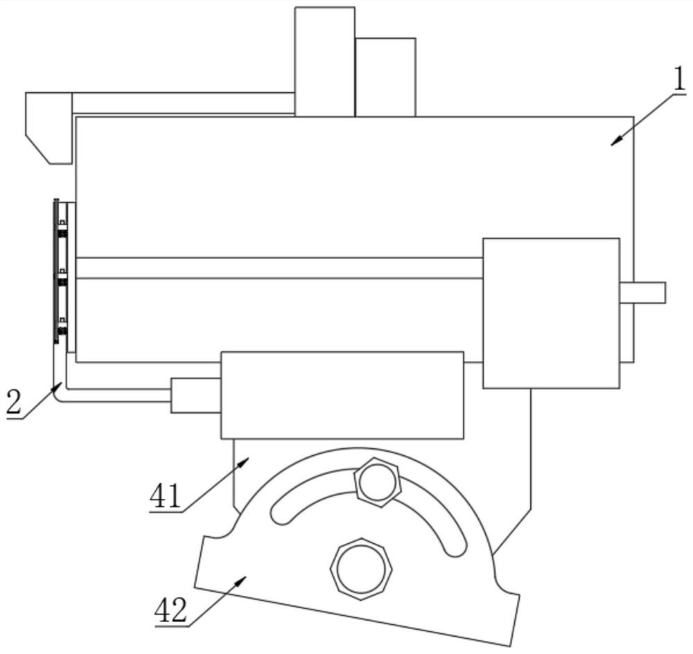
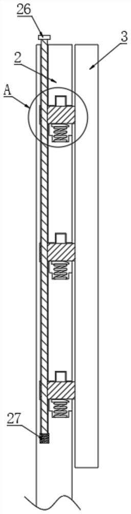
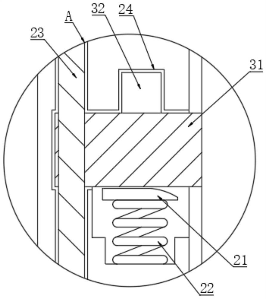
[0025] like Figure 1-Figure 4 As shown, a protection device for a visual inspection system includes a swing rod 2, a replacement mechanism is provided on one side of the swing rod 2, and the replacemen...


PUM


Abstract

The invention discloses a protection device of a visual inspection system, which comprises a swing rod. A replacement mechanism is arranged on the surface of one side of the swing rod, the replacementmechanism comprises a cleaning block, the cleaning block is located on the surface of one side of the swing rod, and a fixing rod is fixedly connected to the surface of one side of the cleaning block, and a clamping block are fixedly connected to the surface of one side of the fixing rod. The fixing rod and the clamping block are located on the inner side of the swing rod, the clamping block is connected with a clamping groove, an abutting block is arranged on the surface of the bottom end of the fixing rod, the surface of one side of the abutting block is of an arc-shaped structure, a secondspring is fixedly connected to the surface of the bottom end of the abutting block, and the abutting block and the second spring are both located on the inner side of the swing rod. A reinforcing rodis connected into the swing rod in a penetrating mode. A reinforcing block is fixedly connected to one side surface of the reinforcing rod. The top end surface of the reinforcing block is movably connected to the bottom end surface of the fixing rod; and through the arranged replacement mechanism, after the device is used for a long time, the cleaning block begins to age until the cleaning blockcannot be used, and at the moment, the cleaning block can be simply and conveniently replaced with a new cleaning block.

Description

technical field [0001] The present invention relates to the technical field of devices for visual inspection, in particular to a protection device for a visual inspection system. Background technique [0002] Belt conveyor is an important equipment for mines, power plants, ports and other enterprises to transport coal, ore and other materials. When a belt tearing accident occurs, if it is not detected and stopped in time, the entire belt will be torn, and the strong belt tension will destroy the reducer, motor, frame and other connected equipment, resulting in huge property losses and even personal safety. In order to solve this technical problem, many methods have been tried at home and abroad for belt tear-proof detection, such as: impact detection method to detect the transmission of impact force in the belt medium, and abnormal force of the roller to analyze the abnormal state of the roller. Detection, ultrasonic method to detect ultrasonic wave propagation in belt medi...

Claims


Application Information

Patent Timeline
Patent Type & Authority Applications(China)
IPC IPC(8): G01N21/01B65G15/32H04N5/225B08B1/00
CPCG01N21/01B65G15/32B08B1/006G01N2201/022B65G2203/0275B65G2203/041H04N23/51
Inventor 查韶辉
Owner HUAQING INTELLIGENT TECH (SUZHOU) CO LTD
Why Eureka
Try Eureka