Valley electricity heat storage steam boiler system

A technology of steam boiler and heat storage, which is applied in steam central heating system, heating system, steam generation, etc., which can solve problems such as increasing economic expenditure, causing smog, and unstable power generation load of small thermal power plants

Pending Publication Date: 2021-03-02
田宇平
View PDF0 Cites 1 Cited by
  • Summary
  • Abstract
  • Description
  • Claims
  • Application Information

AI Technical Summary

Problems solved by technology

[0002] Nowadays, heating is used in many places. For example, coal-fired boilers are used to provide heat to residents in winter in the north. Coal-fired boilers will not only produce a lot of waste gas, cause smog, and pollute the environment; Electric boilers, although the use of electric boilers can effectively solve the problem of environmental pollution, most of them are used during the day, such as important industrial enterprises, hospitals, hotels, etc., which need to supply steam at any time, or the power generation load of small thermal power plants is not stable and the industrial steam load is different. Balance, on the one hand, it will cause pressure on electricity consumption, on the other hand, it will also increase economic expenditure; now it is urgent to use the valley electricity at night to heat the electric boiler, and store it for the steam needed during the day

Method used


Image

  • Valley electricity heat storage steam boiler system

Examples


Embodiment Construction

[0014] The present invention will be further described in detail below in conjunction with the accompanying drawings and specific embodiments.

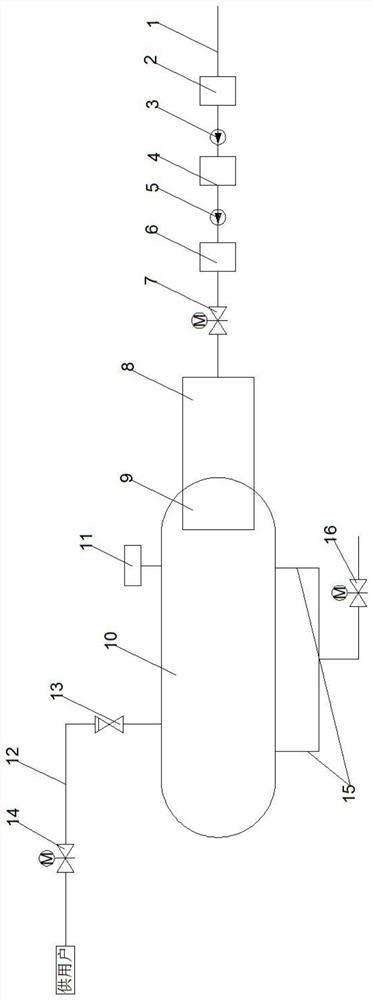
[0015] Such as figure 1 As shown, a valley electricity thermal storage steam boiler system of the present invention is installed in sequence according to the water flow direction on the water treatment system 2 on the water inlet pipe 1, the water treatment water supply pump 3, the softened water tank 4, the softened water supply pump 5, and the liquid level gauge 6 And the water inlet pipeline electric valve 7, the water inlet pipeline electric valve 7 is connected with the vapor-liquid phase change steam heat storage tank 10 through the electric steam boiler 8, and the gas-liquid phase change steam heat storage tank 10 is connected with the electric steam boiler 8 A vapor-liquid conversion device 9 is provided at the end, and a steam supply pipeline 12 is installed on the upper left end of the vapor-liquid phase change steam heat st...


PUM


Abstract

The invention discloses a valley electricity heat storage steam boiler system. According to the valley electricity heat storage steam boiler system, a water treatment system, a water treatment water supply pump, a softened water tank, a softened water supply pump, a liquid level device and a water inlet pipeline electric valve are sequentially arranged on a water inlet pipe according to the waterflow direction, the water inlet pipeline electric valve is connected to a steam-liquid phase change steam heat storage tank through an electric steam boiler, a steam-liquid conversion device is arranged at the connecting end of the steam-liquid phase change steam heat storage tank and the electric steam boiler, a steam supply pipeline is arranged at the upper left end of the steam-liquid phase change steam heat storage tank, a steam supply check valve and a steam supply pneumatic valve are sequentially arranged on the steam supply pipeline in the steam supply direction, a controller is arranged at the upper right end of the steam-liquid phase change steam heat storage tank, a blow-off pipeline is arranged at the bottom end of the steam-liquid phase change steam heat storage tank, and a blow-off electric valve is arranged on the blow-off pipeline. The valley electricity heat storage steam boiler system has the advantages that the electric boiler can be heated by utilizing valley electricity at night and stored for supplying steam required by industrial enterprises in the daytime, and the system is economical, efficient, low-carbon and environmentally-friendly.

Description

technical field [0001] The invention relates to the technical field of heat storage and steam supply, in particular to a valley electricity heat storage steam boiler system. Background technique [0002] Nowadays, heating is used in many places. For example, coal-fired boilers are used to provide heat to residents in winter in the north. Coal-fired boilers will not only produce a lot of waste gas, cause smog, and pollute the environment; Electric boilers, although the use of electric boilers can effectively solve the problem of environmental pollution, most of them are used during the day, such as important industrial enterprises, hospitals, hotels, etc., which need to supply steam at any time, or the power generation load of small thermal power plants is not stable and the industrial steam load is different. Balance, on the one hand, will cause electricity consumption pressure, on the other hand, it will also increase economic expenditure; now it is urgent to use the valley...

Claims


Application Information

Patent Timeline
IPC IPC(8): F22B1/02F22B1/28F24D1/02
CPCF22B1/028F22B1/28F24D1/02
Inventor 田宇平
Owner 田宇平
Why Eureka
Try Eureka