
Soil nail, side slope reinforcing structure and construction method thereof

A technology for strengthening structures and construction methods, which is applied in basic structure engineering, excavation, drainage structures, etc., can solve the problems of insufficient uplift bearing capacity of soil nails, unsatisfactory reinforcement effect, and low construction efficiency of soil nails, so as to shorten the construction period. , excellent cold resistance, the effect of reducing construction costs

Pending Publication Date: 2021-03-02
HARBIN INST OF TECH
View PDF6 Cites 3 Cited by
  • Summary
  • Abstract
  • Description
  • Claims
  • Application Information

AI Technical Summary

Problems solved by technology

[0004] The first purpose of the present invention is to provide a soil nailing structure suitable for slope reinforcement structures to solve the problems of insufficient ultimate pull-out bearing capacity and unsatisfactory reinforcement effect of traditional soil nails
[0005] The second purpose of the present invention is to provide a slope reinforcement structure to solve the problem that the traditional soil nailing slope nodes are not stable and easy to shift
[0006] The third object of the present invention is to provide a construction method of slope reinforcement structure to solve the problem of low efficiency of traditional soil nailing construction

Method used


Image

  • Soil nail, side slope reinforcing structure and construction method thereof
  • Soil nail, side slope reinforcing structure and construction method thereof
  • Soil nail, side slope reinforcing structure and construction method thereof

Examples


specific Embodiment approach 1

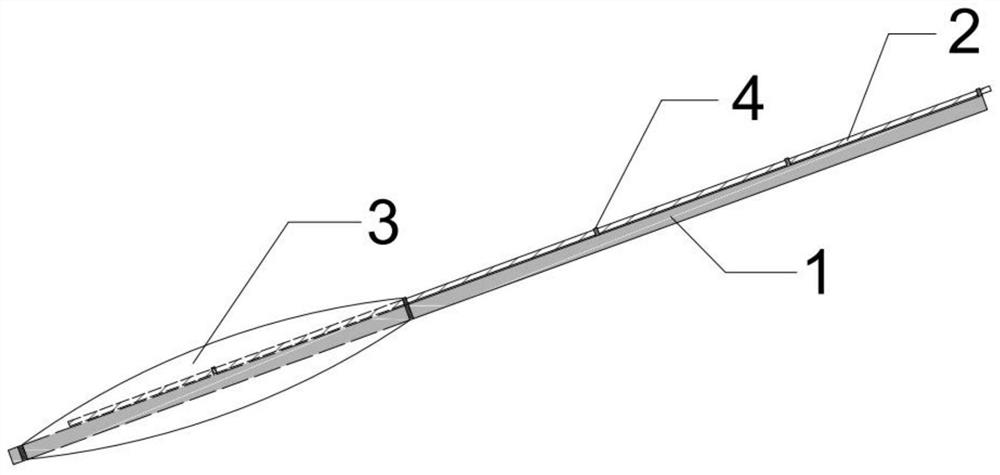
[0045] A soil nail, comprising a core material 1, a grouting pipe 2, a separation bag 3 and several collars 4, the separation bag 3 is fixedly sleeved on the bottom end of the core material 1, and the plurality of collars 4 are fixed on On the side wall of the core material 1 , the grouting pipe 2 is inserted into the partition bag 3 through several collars 4 .

[0046] Further, the bottom end of the core material 1 is set through the partition bag 3 and has a certain extension length at the end of the partition bag 3 . Both ends of the separation bag 3 are fixed on the core material 1. Preferably, the core material 1 (including the collar 4 at the connection) and the separation bag 3 are connected by welding and steel wire binding.

[0047] Further, the plurality of collars 4 are evenly welded and fixed on one side of the core material 1 , preferably, the distance between the collars 4 on the core material 1 is 1 m.

[0048] Further, the bottom end of the grouting pipe 2 is ...

specific Embodiment approach 2

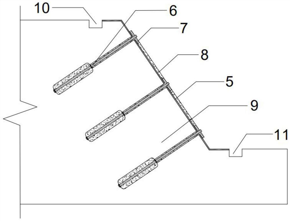
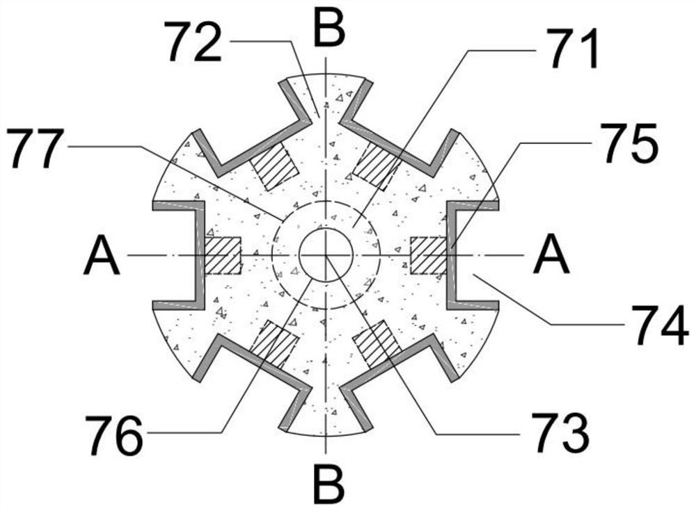
[0052] A slope reinforcement structure comprising the soil nails described in Embodiment 1, comprising a concrete spray layer 5, several soil nails 6, several end connection control members 7 and several prefabricated tie beams 8, the concrete The primary spraying layer 5 is arranged on the surface of the slope body 9, and the several soil nails 6 are inserted into the slope body 9 through the concrete primary spraying layer 5, and the top of each soil nail 6 is controlled by an end connection. The components 7 are fixed, and the adjacent end connection control components 7 are all fixedly connected by prefabricated tie beams 8 . The end connection control member 7 also plays the role of fixing the large-diameter soil nail 6 and connecting the prefabricated tie beam 8 .

[0053] Preferably, the basic unit of the layout shape of the several prefabricated tie beams 8 in the slope reinforcement structure is an equilateral triangle.

[0054]Further, each of the end connection con...

specific Embodiment approach 3

[0060] A construction method of the slope reinforcement structure described in the second embodiment, comprising the following steps:

[0061] Step 1. Carry out geological survey on the railway slope, design the specific size and quantity of the large-diameter soil nail 6, the end connection control member 7 and the prefabricated tie beam 8 according to the engineering requirements, and submit it to the factory for production; clean up the slope The sundries on the slope body 9 are leveled and compacted, a water intercepting ditch 10 is set at the top of the slope, a drainage groove is set on the slope surface, and a drainage ditch 11 is set at the bottom of the slope;

[0062] Step 2, spray a layer of 5mm thick concrete surface layer to the leveled slope body 9 to form the initial concrete spray layer 5;

[0063] Step 3, accurately locate the positions of the first layer and the second layer of soil nails 6 according to the design requirements and add marks at these positions...


PUM


Abstract

The invention relates to a soil nail, a slope reinforcing structure and a construction method thereof, and belongs to the field of side slope engineering. According to the specific scheme, the soil nail comprises a core material, a grouting pipe, a separation bag and a plurality of lantern rings, the bottom end of the core material is fixedly provided with the separation bag in a sleeved mode, thelantern rings are fixed to the side wall of the core material, and the grouting pipe penetrates through the lantern rings to be inserted into the separation bag. The side slope reinforcing structurecomprises a concrete initial spraying layer, a plurality of soil nails, a plurality of end connection control components and a plurality of prefabricated connecting beams, the concrete initial spraying layer is arranged on the surface of a side slope body, the soil nails penetrate through the concrete initial spraying layer to be inserted into the side slope body, the top end of each soil nail isfixed through the corresponding end connection control component, and every two adjacent end connection control components are fixedly connected through the prefabricated connecting beams. According to the side slope reinforcing structure, the large-diameter reinforcing body soil nails are adopted, the number of the soil nails is reduced, meanwhile, the side slope stability is improved, thus the construction period is shortened, and the construction cost is reduced.

Description

technical field [0001] The invention relates to the field of slope engineering, in particular to a soil nail, a slope reinforcement structure and a construction method thereof. Background technique [0002] Due to unfavorable engineering conditions, climatic environment, etc., slopes are very prone to collapses and landslides, which seriously endanger the safety and stability of slopes. Therefore, it is necessary to effectively protect and reinforce slopes that may have diseases. [0003] As a measure of slope protection and reinforcement, soil nailing can strengthen the slope soil and enhance the integrity of the slope, and has been widely used in various types of slopes. However, the traditional soil nailing slope protection technology still has the following disadvantages: (1) The nodes on the soil nailing slope are not stable and are prone to displacement; (2) The ultimate pull-out bearing capacity of the soil nails is insufficient, and the reinforcement effect is not i...

Claims


Application Information

Patent Timeline
Patent Type & Authority Applications(China)
IPC IPC(8): E02D17/20E02D3/12E03F5/04
CPCE02D3/12E02D17/20E03F5/04Y02A30/60
Inventor 凌贤长丛晟亦朱磊唐亮邢文强耿琳程志和胡意如
Owner HARBIN INST OF TECH
Learn More