
Lifting mechanism and civil engineering steel truss erecting device

A lifting mechanism and civil engineering technology, applied in the direction of lifting devices, lifting frames, etc., can solve the problems of inability to secure steel trusses, troubles, heavy lifting devices, etc., and achieve the effect of convenient erection process and easy installation

Active Publication Date: 2021-03-02
NANYANG NORMAL UNIV
View PDF11 Cites 0 Cited by
  • Summary
  • Abstract
  • Description
  • Claims
  • Application Information

AI Technical Summary

Problems solved by technology

[0004] 1. It is difficult for the existing lifting device to keep the steel truss balanced and stable, especially when fixing the steel truss, it is necessary to ensure that the steel truss is stable, otherwise it is difficult to complete the assembly process;
[0005] 2. After using the lifting device to lift the steel truss to a certain height, it is impossible to ensure that the ends of the steel truss are aligned with the parts that need to be assembled, so the operator needs to move the lifting device repeatedly, so that the position of the steel truss is convenient for the operator to fix, but the lifting The device is heavy, and it is difficult to fine-tune it accurately, so it is quite troublesome for the erection process

Method used


Image

  • Lifting mechanism and civil engineering steel truss erecting device
  • Lifting mechanism and civil engineering steel truss erecting device
  • Lifting mechanism and civil engineering steel truss erecting device

Examples


Embodiment

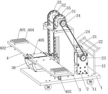
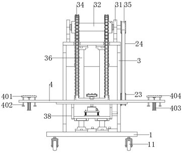
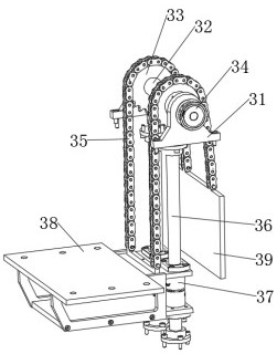
[0028] Example: see Figure 1-5 , a lifting mechanism, comprising a mounting bracket 2 and a lifting platform 3 arranged in front of the mounting bracket 2, both sides of the interior of the lifting platform 3 are vertically provided with columns 36, and the front of the lifting platform 3 is provided with a top surface Keep the horizontal bearing frame 38, the two ends of the column 36 are respectively fixedly connected to the inner top surface and the inner bottom surface of the lifting platform 3, the column 36 is provided with sliding sleeves 37, and the sliding sleeves 37 are fixedly connected to the bearing frame 38; The sliding sleeve 37 is a short tubular structure, which is slidably sleeved on the column 36, so that the bearing frame 38 can be lifted up and down along the column 36 to lift the steel truss.

[0029] Both sides of the top surface of the lifting platform 3 are provided with fixed mounts 31, and above the top surface of the lifting platform 3, a rotating ...


PUM


Abstract

The invention relates to the technical field of civil engineering, in particular to a lifting mechanism and a civil engineering steel truss erecting device.The lifting mechanism comprises an installation support and a lifting table arranged in front of the installation support, stand columns are vertically arranged on the two sides of the interior of the lifting table, and a bearing frame with thetop face kept horizontal is arranged in front of the lifting table; and the two ends of the stand columns are fixedly connected to the inner top face and the inner bottom face of the lifting table respectively, the stand columns are sleeved with sliding sleeves, and the sliding sleeves are fixedly connected with the bearing frame. According to the lifting mechanism, the bearing frame used for containing a steel truss can slide up and down in the vertical plane along the stand columns, so that stable lifting of the steel truss is kept, and troubles caused by shaking and instability in the erecting process are avoided.

Description

technical field [0001] The invention relates to the technical field of civil engineering, in particular to a lifting mechanism and a civil engineering steel truss erection device. Background technique [0002] Civil engineering refers to the general designation of science and technology for the construction of various engineering facilities. It includes materials, equipment, and technical activities such as surveying, design, construction, maintenance, and repair. It also refers to the object of engineering construction, that is, it is built on the ground or underground. , Land or water, various engineering facilities that directly or indirectly serve human life, production, military affairs, and scientific research. The truss refers to a structure composed of rods connected by hinges at both ends. It is usually a plane or space structure with triangular units composed of straight rods. The truss rods mainly bear axial tension or pressure, so that It can make full use of th...

Claims


Application Information

Patent Timeline
Patent Type & Authority Applications(China)
IPC IPC(8): B66F7/02B66F7/28
CPCB66F7/02B66F7/28
Inventor 李瑞李科王宗华
Owner NANYANG NORMAL UNIV
Learn More