
Drilling equipment for portable heat insulation plate

A drilling equipment and plate technology, applied in drilling/drilling equipment, boring/drilling, metal processing equipment, etc., can solve the problems of convenient insulation board position offset, drilling offset, flapping and other problems

Inactive Publication Date: 2021-03-02
北京春合隅林建筑工程有限公司
View PDF0 Cites 0 Cited by
  • Summary
  • Abstract
  • Description
  • Claims
  • Application Information

AI Technical Summary

Problems solved by technology

[0003] Due to the lightness of the convenient heat insulation board, if the drilling machine for the portable heat insulation board needs to drill two convenient heat insulation boards at the same time due to the tight working hours, the upper convenient heat insulation board will be drilled when it is drilled. The phenomenon of vibrating and beating the lower heat shield will cause the position of the convenient heat shield that is not drilled in the lower layer to gradually shift, resulting in the drilling deviation of the drill bit when drilling into the lower heat shield

Method used


Image

  • Drilling equipment for portable heat insulation plate
  • Drilling equipment for portable heat insulation plate
  • Drilling equipment for portable heat insulation plate

Examples


Embodiment 1

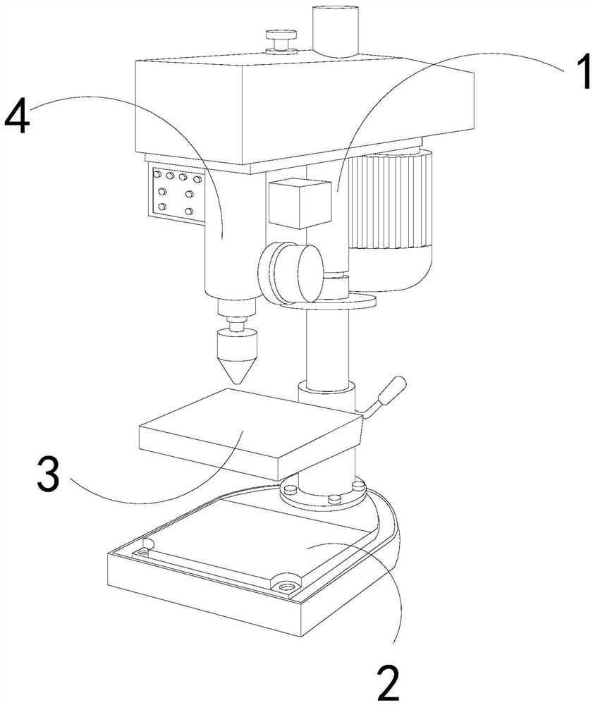
[0026] For example figure 1 -example Figure 5 Shown:

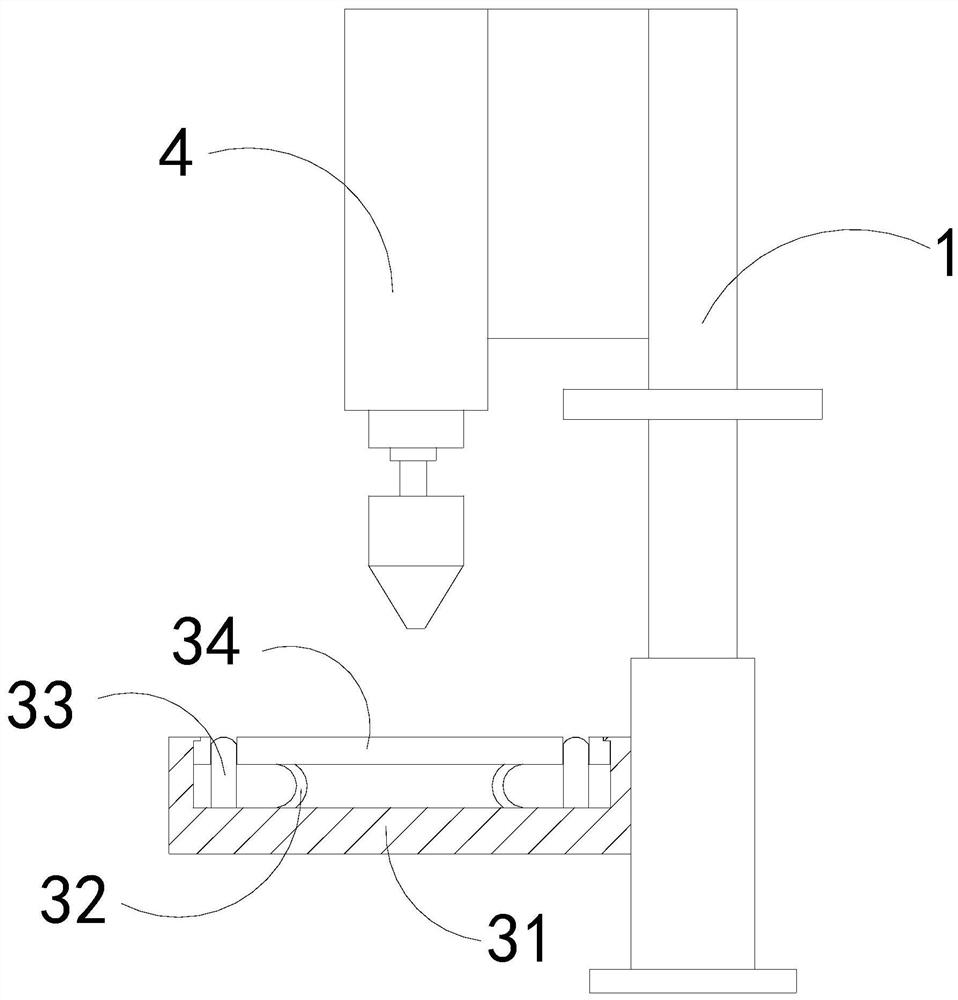
[0027] The invention provides a drilling device for portable heat-insulating boards, the structure of which includes a support rod 1, a base 2, an operating table 3, and a drill bit 4, the support rod 1 is embedded in the upper end of the base 2, and the drill bit 4 is installed At the front end of the support rod 1, the operating table 3 is welded to the supporting rod 1; the operating table 3 includes a bottom plate 31, an elastic sheet 32, an outstretched rod 33, and a force plate 34, and the elastic sheet 32 ​​is installed on Between the bottom of the force plate 34 and the base plate 31, the bottom of the outrigger 33 is embedded and connected with the bottom of the inner wall of the base plate 31, and the outrigger 33 is in clearance fit with the force plate 34, and the force plate 34 It is movably engaged with the base plate 31 .

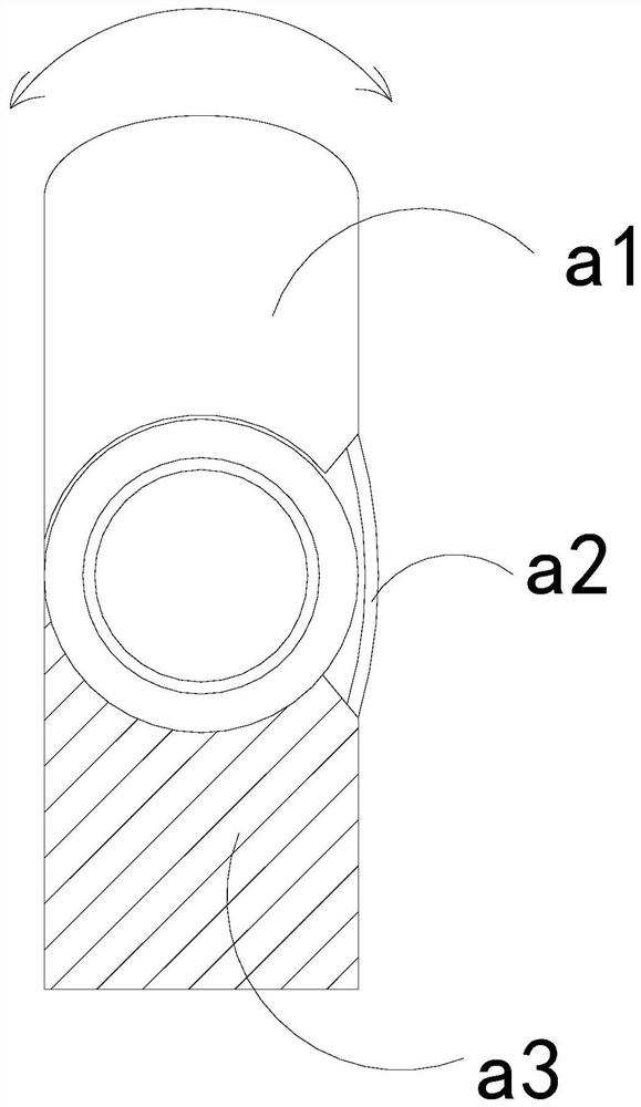
[0028] Wherein, the outrigger 33 includes a single pendulum plate a1, a reset pie...

Embodiment 2

[0034] For example Figure 6 -example Figure 8 Shown:

[0035] Wherein, the force bearing plate 34 includes a suction plate c1, an upper touch plate c2, a sealing block c3, and a bottom frame c4. The bottom frame c4 is movable, and the sealing block c3 is installed at the bottom of the inner wall of the bottom frame c4. There are four adsorption plates c1, which are evenly distributed in parallel on the upper touch plate c2. The extrusion of the plate against the upper contact plate c2 can make the upper contact plate c2 shrink downward along the bottom frame c4, so that the sealing block c3 can seal the middle part of the suction disk c1, so that the suction disk c1 can be adsorbed on The bottom of the Portable Heat Shield.

[0036] Wherein, the suction plate c1 includes an upper connection plate c11, a deformation block c12, a booster bar c13, and a receiving plate c14. The deformation block c12 is installed between the upper connection plate c11 and the receiving plate ...


PUM


Abstract

The invention discloses drilling equipment for a portable heat insulation plate. The equipment structurally comprises a supporting rod, a base, an operation table and a drill bit, wherein the supporting rod is fixedly embedded in the upper end of the base, the drill bit is installed at the front end of the supporting rod, and the operation table is welded to the supporting rod. By means of the pressure generated on the portable heat insulation plate on the operation table by the drill bit when the drill bit descends, a stressed plate can contract downwards along a bottom plate, an outwards-extending rod can extend out upwards along the stressed plate, the outwards-extending rod can be attached to the side face of the portable heat insulation plate, and thus the situation that when two portable heat insulation plates are subjected to drilling together, the portable heat insulation plate on the lower layer vibrates and deviates is effectively avoided; and a suction disc can be sucked atthe bottom of the portable heat insulation plate through continuous extrusion by the portable heat insulation plate to the suction disc, and therefore the situation that the portable heat insulation plate with the small size is not prone to be fixed through two outwards-extending rods, and thus the portable heat insulation plate vibrates and deviates can be effectively avoided.

Description

technical field [0001] The invention relates to the field of drilling, in particular to a drilling device for portable heat-insulating boards. Background technique [0002] The portable heat insulation board drilling machine is mainly used for drilling convenient heat insulation boards. The drill bit is pushed down by the lifting push rod, so that the high-speed rotating drill bit can drill specified specifications on the convenient heat insulation board. Based on the above description, the inventors found that the existing drilling equipment for portable heat insulation boards mainly has the following deficiencies, for example: [0003] Due to the lightness of the convenient heat insulation board, if the drilling machine for the portable heat insulation board needs to drill two convenient heat insulation boards at the same time due to the tight working hours, the upper convenient heat insulation board will be drilled when it is drilled. The phenomenon of vibrating and beat...

Claims


Application Information

Patent Timeline
Patent Type & Authority Applications(China)
IPC IPC(8): B23B41/00B23B47/00B23Q3/08B23Q11/00
CPCB23B41/00B23B47/00B23Q3/088B23Q11/0032
Inventor 罗家春
Owner 北京春合隅林建筑工程有限公司
Learn More