
An embroidery machine laser control device and method

An embroidery machine and laser technology, which is applied to embroidery machines, embroidery machine mechanisms, automatic control embroidery machines, etc., can solve the problems of low efficiency of model change, inability to save parameters, inconvenient operation, etc., and achieve simple setting, upgrade and change Efficiency and easy operation

Active Publication Date: 2022-03-08
ZHEJIANG XINSHENG SEWING EQUIP
View PDF10 Cites 0 Cited by
  • Summary
  • Abstract
  • Description
  • Claims
  • Application Information

AI Technical Summary

Problems solved by technology

Very inconvenient to operate, especially for multi-head embroidery machines
[0004] After setting up product A, switch to product B after processing, the laser parameters need to be reset. extremely inefficient

Method used


Image

  • An embroidery machine laser control device and method
  • An embroidery machine laser control device and method
  • An embroidery machine laser control device and method

Examples


Embodiment 1

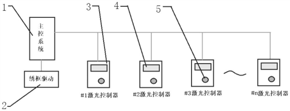
[0031] Such as figure 1 As shown, an embroidery machine laser control device includes an embroidery machine main control system 1, an embroidery frame drive system 2 communicating with the embroidery machine main control system, and a communication connection with the embroidery machine main control system 1 and corresponding to each machine head. A laser controller 3 provided separately for the laser heads. The laser controller 3 is provided with a power display screen 4 and a power fine-tuning knob 5 .

[0032] Wherein, the main control system 1 of the embroidery machine is provided with an embroidery parameter storage module and a pattern parameter calling module, and the embroidery parameter storage module stores embroidery frame speed parameters and laser power parameters of each laser controller corresponding to each pattern, so The above-mentioned pattern parameter calling module writes the corresponding embroidery frame speed parameters into the embroidery frame drive...

Embodiment 2

[0036] A laser control method for an embroidery machine, comprising the following steps in sequence:

[0037] Embroidery parameter storage: store the embroidery frame speed parameters corresponding to each pattern and the laser power parameters of each laser controller in the embroidery parameter storage module of the main control system of the embroidery machine;

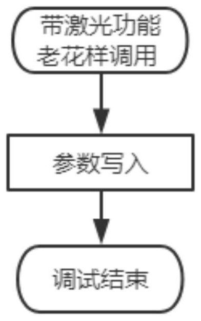
[0038] Pattern parameter call: After any pattern is called, write the corresponding frame speed parameters into the frame drive system, and write the laser power parameters of each laser controller into the corresponding laser controller according to the address;

[0039] Laser embroidery: During the laser embroidery process, the embroidery frame drive system drives the embroidery frame according to the written embroidery frame speed parameters, and each laser controller controls the laser head according to the corresponding laser power parameters.

[0040] The frame speed parameters corresponding to each pattern a...


PUM


Abstract

The invention discloses an embroidery machine laser control device and method. The device comprises an embroidery machine main control system, an embroidery frame drive system communicated with the embroidery machine main control system, a communication connection with the embroidery machine main control system and corresponding to each machine control system. Laser controllers are set separately for the laser heads of the head. The main control system of the embroidery machine is equipped with an embroidery parameter storage module and a pattern parameter calling module. The power parameter and pattern parameter calling module writes the corresponding embroidery frame speed parameter into the embroidery frame drive system after any pattern is called, and writes the laser power parameter of each laser controller into the corresponding laser controller according to the address. The invention can directly call the old patterns processed before, and write the parameters to each machine head, which saves the process of resetting parameters and fine-tuning the laser head of each machine head, and significantly improves the efficiency of model change .

Description

technical field [0001] The invention relates to the technical field of laser embroidery. Background technique [0002] The matching laser device of the existing embroidery machine is simple to control, only has start and stop signals, and the debugging is complicated and takes a long time. [0003] The electric control parameters of the laser and the embroidery machine are independent. The electric control adjusts the embroidery speed parameters when the laser is in operation. Each laser head is equipped with a regulator to adjust the power: the operator first manually adjusts the power regulator of each machine head to The corresponding power value, and then set the speed parameters in the main control system according to the cloth. Then test the machine to get more practical results, and then adjust the laser parameters of each head. It is very inconvenient to operate, especially for multi-head embroidery machines. [0004] After setting up product A, switch to product ...

Claims


Application Information

Patent Timeline
Patent Type & Authority Patents(China)
IPC IPC(8): D05C7/10D05C5/06
CPCD05C7/10D05C5/06
Inventor 王海江郭浩烽周迪标
Owner ZHEJIANG XINSHENG SEWING EQUIP
Learn More