Work station apparatus for steel stealing prevention
A station appliance and steel technology, which is applied in the field of steel anti-theft station appliances, can solve the problems of affecting work progress and cumbersome unloading process, etc.
- Summary
- Abstract
- Description
- Claims
- Application Information
AI Technical Summary
Problems solved by technology
Method used
Image
Examples
Embodiment 1
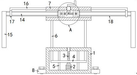
[0022] Example 1 as figure 1 As shown, a station appliance for anti-theft of steel includes a base 1, a first cavity is opened inside the base 1, a motor 2 is fixed inside the first cavity, and the output end of the motor 2 is fixedly connected with a wire Rod 3, the upper end rod wall of the screw rod 3 is rotatably connected with the upper surface of the first cavity through the first bearing, and a mounting plate 4 is arranged inside the first cavity, and the mounting plate 4 is threadedly connected with the rod wall of the screw rod 3 and the inside Two limit holes are symmetrically opened, and the insides of the two limit holes are respectively movably socketed with limit rods 5, and the two ends of each limit rod 5 are respectively fixedly connected with the upper and lower surfaces of the first cavity. Four through holes are symmetrically opened on the upper surface of a cavity, four support rods 6 are symmetrically fixed on the upper surface of the mounting plate 4, an...
Embodiment 2
[0023] Embodiment 2 is on the basis of embodiment 1 such as figure 2 As shown, the driving mechanism includes a two-way screw rod 9, a rotating rod 10 and two fixed plates 11, and the two fixed plates 11 are symmetrically fixed inside the second cavity, and the two ends of the two-way screw rod 9 pass through the second rod wall respectively. The bearing is rotatably connected with the side wall of the corresponding fixed plate 11, the upper end rod wall of the rotating rod 10 is rotatably connected with the upper surface of the second cavity through the third bearing and the lower end is fixedly connected with the first bevel gear 12, the two-way screw rod 9 The rod wall is fixedly sleeved with the second bevel gear 13 and meshed with the first bevel gear 12 .
Embodiment 3
[0024] Embodiment 3 is such as on the basis of embodiment 1 figure 2 As shown, the clamping mechanism includes two internally threaded sleeves 14 and two clamping plates 15, and the two internally threaded sleeves 14 are symmetrically arranged inside the second cavity and are threaded with the two ends of the two-way screw rod 9 respectively. To connect, the opposite ends of the two internally threaded sleeves 14 are respectively fixedly connected to the corresponding clamping plates 15, so as to facilitate the clamping of steel materials.
PUM
 Abstract
Description
Claims
Application Information
 - R&D
- Intellectual Property
- Life Sciences
- Materials
- Tech Scout
- Unparalleled Data Quality
- Higher Quality Content
- 60% Fewer Hallucinations
Browse by: Latest US Patents, China's latest patents, Technical Efficacy Thesaurus, Application Domain, Technology Topic, Popular Technical Reports.
© 2025 PatSnap. All rights reserved.Legal|Privacy policy|Modern Slavery Act Transparency Statement|Sitemap|About US| Contact US: help@patsnap.com


